2020 November 7
Understanding image defects

Trailed stars
Trailed stars are result of imperfect polar alignment, drive errors, vibration from wind or other sources, or lack of rigidity in the optical train. Whether errors become visible is function of focal length and pixel size (i.e. image scale), and exposure time. With imperfect polar alignment or poor driving, you can compensate by using shorter exposures or reducing the focal length (which is done on refractors and Schmidt Cassegrains using a focal reducer).
The route to obtaining good tracking begins with having a mount that is adequate for the telescope, which means it should be over-specified by the standards that telescope manufacturers usually recommend. While, with modern cameras, considerable success is possible on high surface brightness deep sky objects such as planetary nebulae and globular clusters using exposures as short as a few seconds, and stacking many images, imaging of low surface brightness objects such as diffuse nebulae and galaxies requires exposures that last minutes. For this, there is still no good alternative to the German Equatorial Mount (GEM), and if you are serious about this type of imaging, I recommend spending more on the mount than on the telescope.
A good GEM will have an average tracking exactly matching sidereal rate, but those driven by the traditional worm and gearwheel will still have a small acceleration and deceleration once per turn of the worm, due to its being not quite circular – this is the periodic error. The best GEMs reduce this error to a few seconds of arc, which can be regarded as negligible except with focal lengths of over 2m. Trailing can also be due to shift of optics in their cells (particularly a problem with SCTs), flexure, or, loose coupling of components. Even if all these are eliminated, the sky itself produces an image shift: objects are refracted upwards more as they approach the horizon.
The most precise tracking requires an autoguiding system, whereby an image of a guide star on a secondary detector is monitored on a short time cycle (a few seconds), with shifts of position of this star on the detector, too small to affect the main image, being used to generate a guiding signal that speeds up or slows down the mount, and nudges it in declination, to keep the imaging on track. Autoguiding is best not used as a substitute for accurate polar alignment, however, and periodic error correction (obtained by recording the worm error over a cycle and programming compensation in to the control system) may be tried first.
Blurred or distorted stars at the image edges
There are a number of possible effects in this category. Assuming you have achieved perfect focus at the image centre, if you see the stars go out of focus towards all the image edges symmetrically, but remain round, you have field curvature. This is present in refractors, particularly faster ones (below f/8) and SCTs, and always becomes more noticeable as the detector becomes larger. It is corrected with a lens called a focal reducer or field flattener (the same lens normally having both effects). For optimum results the flattener needs to be engineered to the specific telescope (though those for SCTs giving x0.63 focal reduction are generic), and the flattener to detector distance needs to be correct – for most, 55mm is recommended, but a few millimetres error is probably not noticeably detrimental. If the flattening is not perfect, best results may be obtained with focusing that compromises between the centre and edges of the field.
With Newtonians, particularly those faster than f/5, a different defect predominates: a comet-shaped distortion of stars at the edges of the field. This is coma, and again it becomes more of a problem with larger detectors, such as those in DSLRs. It is treated with a coma corrector, which again requires the correct lens to detector distance for optimum results. Coma correctors may increase or decrease the effective focal ratio slightly, and in practice there can be an issue with having enough inward travel on the Newtonian focuser. In theory they correct perfectly only for one specific focal ratio, but in practice are quite good over a range.
 It is often found, however, that star distortions are not symmetric across the image: those in one corner of the image may be sharper than those in another corner, and stars in different parts of the image may have distortions of different shapes. These effects (assuming the optics are well-made) are a consequence of miscollimation (misalignment) of some kind. If they are combined with slight star trailing, the situation may be confusing to diagnose. If these errors cannot be eliminated by re-collimating the telescope, the fault will be that some other part of the imaging train is not square-on to the optical axis. The detectors in astronomical cameras can sometimes be not square-on, with resulting distortions that become visible at low focal ratios. Sometimes the mounting of the detector is slightly adjustable with screws, if you wish to risk delving inside the camera (which might invalidate a warranty). You can also square the detector on using a camera tilt adjuster, which is a pair of threaded rings with push-pull adjustment screws, that is fitted into the imaging train immediately in front of the camera.
Hot, dead and stuck pixels
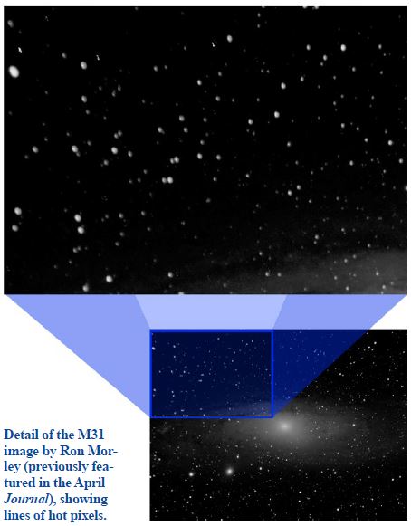 Close examination of the image of M31 above shows, in addition to the distorted stars, some bright streaks only 1-2 pixels wide. These are due to ‘hot pixels’ in the camera detector: pixels that are always give a high output even when little light falls on them. They are a fact of life in semiconductor arrays, with always a few even in the best and newest cameras. They have turned into streaks in the image because a number of sub-exposures (‘subs’) have been stacked on the stars, and the stars have drifted slightly in the field, so the hot pixels have moved in the stacked image. The reverse of a hot pixel is a black, or dead one, that gives very low or zero output. These tend not to be so noticeable in deep-sky imaging, but they can occur. DSLRs also get stuck pixels, which result in coloured spots.
The effects of hot and stuck pixels can be minimised by subtracting from each of the subs, before stacking, the signal from every pixel, measured for the same exposure and temperature, with no light falling on the detector. This is known as dark frame (or dark field) subtraction. The dark frame used for the subtraction is, ideally, an average of many dark frames taken under the same conditions. Dark frames are taken with the telescope or lens aperture covered, or with the camera shutter closed. The optical system does not matter, as there is no light entering it; the process is merely a characterisation of the camera. The process of subtraction is done by specialist astro-imaging software: a free package that does this is DeepSkyStacker (for Windows).
Dark subtraction deals with hot pixels and the amplifier glow that is visible on the detectors of DSLRs in long exposures. Dead pixels will still look dead, however, and stuck pixels will produce black spaces after subtraction. If a dark frame exposed for longer than the light frame, or one exposed when the detector temperature was higher, is used, then there may be over-subtraction, and dark holes may be created in the final image. Temperature should not be an issue with most modern cooled astro cameras, that have fixed-point cooling, but it is with DSLRs, which get hotter the longer they are used. The effect of slightly imperfect tracking is, fortunately, to reduce the visibility of these pixel irregularities, after the subs are stacked on the stars. Once taken, dark frames for a particular exposure and temperature may be re-used, until the characteristics of the detector change with age.
Gradients, vignetting and dust
The result of stacking long exposure subs will be an average image with less noise than the subs contain individually, that can be stretched much further: that is, the difference between the dimmest and brightest pixel values can be mapped, using image-processing software, to a far wider range of brightnesses in the final image. There will be a floor level of brightness of the stacked image, due to sky glow and light pollution, that is far above zero, but this needs to be rendered close to zero in the final image. In fact the statistical profile of images taken in a light-polluted location can often show only a small signal on a high base of pollution noise. Nevertheless, even these images can process well, provided the base to be removed is uniform. If parts of it are brighter than others, then gradients of sky brightness will remain in the final image.
Non-uniformity of the illumination is due to parts of the detector toward the edges not having a light path from the whole aperture – this is known as vignetting – and dirt on the detector, or other factors, reducing sensitivity in places. More complicated optical designs, such as Schmidt Cassegrains, suffer more vignetting than simple lenses and refractors. Dust on the detector, or close to it (e.g. on filters) typically shows up, in telescopes with a secondary mirror, as a dark ring or doughnut on the image, a shadow of the aperture.
Vignetting, and all but the worst effects of contamination, can be dealt with by taking a flat field or frame: this is a very short exposure (a fraction of a second) with the aperture exposed to uniform illumination. Flat fields can be taken on a cloudless twilight sky, or by covering the aperture with an illuminated diffusing cloth, or using a specially constructed luminescent screen. As with dark frames, a good number (more than 10) need to be taken, to average out the response. The exposure needs to be chosen so the signal is high but no pixels are saturated (over-exposed).
 taken on a twilight sky by a DSLR on a 254mm Newtonian, showing typical vignetting and dust effects")
Flat-fielding also reduces the effect of dead pixels, and, with colour cameras, can correct for a gradient of colour that may arise when light passes through a fast (low f/ratio) optical system and an interference filter (e.g. one made to suppress light pollution). It cannot, however, correct for gradients of illumination or colour that are due to the sky, for example, light pollution approaching the horizon, or moonlight. Processing software can help with this, notably Russell Croman’s Photoshop plug-in GradientXterminator.
David Arditti, Director
Equipment & Techniques Section
https://britastro.org/wp-content/uploads/2020/11/DT-5.JPG
| The British Astronomical Association supports amateur astronomers around the UK and the rest of the world. Find out more about the BAA or join us. |