Solar prominences as markers of the Sun’s poloidal magnetic field
2020 March 30
Introduction
Since filaments (seen as dark lines on the solar disc) constitute the longitudinal axes of prominences, the author decided to use day-to-day shifts in prominence position to track the alignment of their respective filaments. All filaments lie along the neutral boundaries between magnetic fields of opposite polarity,1 and a line at right angles to the long axis of any filament (or section of filament) defines the direction of the Sun’s ‘surface’ magnetic field at that location.2
In this study, the shifts in latitude and longitude of 1,577 pairs of prominences seen day to day over nine years (2010–’18) were recorded. For each pair, the author derived the bearing angle that the corresponding filament made with the Sun’s meridian, and the direction of the magnetic field in degrees of arc eastward or westward of this N–S line. The distribution and mean direction of the Sun’s poloidal (N–S) magnetic field, in so far as it was manifested by filament formation, was then plotted for the whole of the nine-year period.
Observing methods & definitions
A Coronado H-alpha PST (Personal Solar Telescope; magnification ×32) was used, which was fitted with a rotating reticle to measure prominence position angles around the Sun’s disc. These were reproducible to ±1°, and were converted to true heliographic latitudes for analysis. Full details of observing methods are contained in a previous Journal article.3
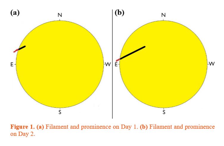 Pairs of prominences seen day to day at similar latitudes, within defined limits,3 mark the ends of a section of a filament and its corresponding magnetic field boundary. The prominence seen on Day 1 marks the western end of a given filament section, and the Day 2 prominence its eastern end. Prominences related to each other in this way, and seen approximately 24 hours apart, will be termed prominence pairs. A prominence pair and related filament are illustrated schematically in Figures 1(a) & 1(b).
Prominence latitude shifts fall into three categories (illustrated in Figure 2):
(i) The Day 2 prominence is seen at a higher latitude than the Day 1 prominence. The corresponding filament/boundary is orientated poleward and eastward from the equator, and its field direction lies at right angles i. e. poleward and westward. These filaments will be termed westward-diverging.
(ii) The Day 2 prominence is seen at a lower latitude than the Day 1 prominence. The corresponding filament/boundary is orientated poleward and westward from the equator, and its field direction lies poleward and eastward. These filaments will be termed eastward-diverging.
(iii) Some prominence pairs show no detectable latitude shift. They therefore mark the positions of filaments lying parallel to the solar equator, with their field directions aligned with the Sun’s N–S meridian. These will be termed meridional. Note however that it was not possible to detect very small shifts in latitude, so some of these meridional filaments may in fact have had magnetic field lines directed slightly east or west of the N–S line.
Analytical methods
The bearing angle with respect to the meridian for each westward- or eastward-diverging filament/boundary, and hence its field direction, was calculated from the latitude and longitude positions of the corresponding prominence pair. This process was carried out in three stages:
(i) The latitudes of the two related prominences were measured by direct observation.
(ii) The separation of the two prominences in longitude was then calculated by using the Sun’s synodic differential rotation rate at the prominence pair’s mean latitude,4 and the time interval between the Day 1 and Day 2 observations.
(iii) Finally, the filament’s bearing (or angle with respect to the meridian) was obtained from these coordinates by spherical trigonometry. Fortunately, the calculation is exactly analogous to the one used for finding a terrestrial bearing from true north (a ‘rhumb line’), given two locations defined by their latitude and longitude. Both the mathematical expression required and a programmed calculating tool are available online.5
Each filament’s magnetic field direction lies at right angles to the filament’s bearing. The angle made between this field direction (eastward or westward) and the Sun’s meridian is termed its divergence angle.
(Login or click above to view the full illustrated article in PDF format)
https://britastro.org/wp-content/uploads/2020/03/Fig1_0.JPG
https://britastro.org/wp-content/uploads/2020/03/Fig1_0.JPG
https://britastro.org/wp-content/uploads/2020/03/Fig1_0.JPG
https://britastro.org/wp-content/uploads/2020/03/Fig1_0.JPG
https://britastro.org/wp-content/uploads/2020/03/Fig1_0.JPG
https://britastro.org/wp-content/uploads/2020/03/Fig1_0.JPG
https://britastro.org/wp-content/uploads/2020/03/Fig1_0.JPG
https://britastro.org/wp-content/uploads/2020/03/Fig1_0.JPG
https://britastro.org/wp-content/uploads/2020/03/Fig1_0.JPG
https://britastro.org/wp-content/uploads/2020/03/Fig1_0.JPG
| The British Astronomical Association supports amateur astronomers around the UK and the rest of the world. Find out more about the BAA or join us. |