UK Radio Meteor Beacon
2022 October 6
Introduction
The UK Meteor Beacon (call sign GB3MBA:‘Meteor Beacon for Astronomy’) is a collaborative project between the UK amateur radio and radio astronomy communities, to facilitate the study of meteor events above the UK. Funding has been provided by the Radio Society of Great Britain (RSGB) Legacy Fund, while the Mansfield & Sutton Astronomical Society have kindly agreed to host the beacon at their Sherwood Observatory. Running costs will be supported by the radio astronomy community, and the beacon was built by amateur radio volunteers.
The beacon transmitter, operating on a frequency of 50.408MHz, is directed vertically upwards with a beamwidth sufficient to illuminate a region with a diameter of about 400km, centred above the observatory. This region is at an altitude of 90 to 100km, where meteors burn up due to friction with the atmosphere, briefly creating an ionised trail that is reflective to radio as they do so. Radio reflections from the ionised trails can be observed to a distance of about 1,200km from the observatory. An advantage of making meteor observations by radio is that such observations are largely independent of weather conditions and can be made equally well by day and night. The operational status of the installation and further information can be found at the beacon website.1
In addition to facilitating academic and citizen-science studies of meteors, a key aim of the project is to build on the widespread interest in space to develop STEM-related projects for schools, attracting young people into radio engineering and astronomy.
Meteor radio basics
My introduction to meteor observation by radio was through using reflections from the GRAVES radar in France.2 Operating on 143.050MHz, just below the two-metre amateur band, I coupled my existing receiver with Spectran to provide a waterfall display and this sparked my interest in meteors.3 Visitors to my radio room, seeing the echoes from meteors displayed on the computer screen, were also fascinated.
I then started to make observations using the BRAMS and VVS meteor beacons in Belgium,4 which operate on 49.970MHz and 49.990MHz, respectively. The observing experience at this longer wavelength (6m) was quite different to that using GRAVES, with a wavelength of 2m. This is in part due to differences in reflectivity with frequency/wavelength of the ionisation created as meteors burn up, and partly due to geometry. But these systems provide few opportunities to observe meteor events above the UK, so the idea of creating our own UK beacon was born.
As meteors burn up, they briefly produce an ionised trail reflective to radio. This behaves like a wire following the meteor and gives rise to reflections (echoes) known, slightly confusingly, as ‘head echoes’. (See Figure 2.) They are very brief – less than one second in duration – and exhibit rapid Doppler shift as the meteor is decelerated due to friction. Reflections from this thin trail of ionisation are polarised and directional, so depending on the angle from which the trail is ‘viewed’, not all observers will see a head echo.
Passage of the meteor through this region of the ionosphere often triggers it to become sufficiently ionised, locally, to be reflective to radio for a longer period of time. Reflections from these regions are more or less isotropic, exhibit little Doppler shift and are known in astronomy circles as ‘tail echoes’. (See Figure 3.) It is reflections from these regions that are used by radio amateurs and others to extend the range of very-high-frequency (VHF) radio communications far beyond the horizon, a propagation mode known as meteor scatter (MS).
The head or fireball of most meteors has a radar cross-section too small to give echoes at this wavelength, while the reflective region giving rise to tail echoes has a larger volume, reflects more or less isotropically and may also have refractive properties. Reflections from different parts of the reflective volume give rise to some spectral spreading, as is the case with other scatter modes of radio propagation. The small, relatively stable Doppler shift which is sometimes observed is due to wind.
Phase I of this project has been to build and deploy the beacon transmitter; this was accomplished on 2022 May 14. Phase II is to design and build a network of web-based receivers deployed to different locations, so that meteor events can be observed from multiple directions. Measurements of the Doppler shift of head echoes at a particular instant, observed from different directions, can then be used to calculate the location and trajectory of meteors. The amount of shift is a function of the rate at which the path from the transmit beacon to the meteor and onwards to the receiver is reducing, giving rise to a positive shift, or extending, giving a negative shift.
The beacon
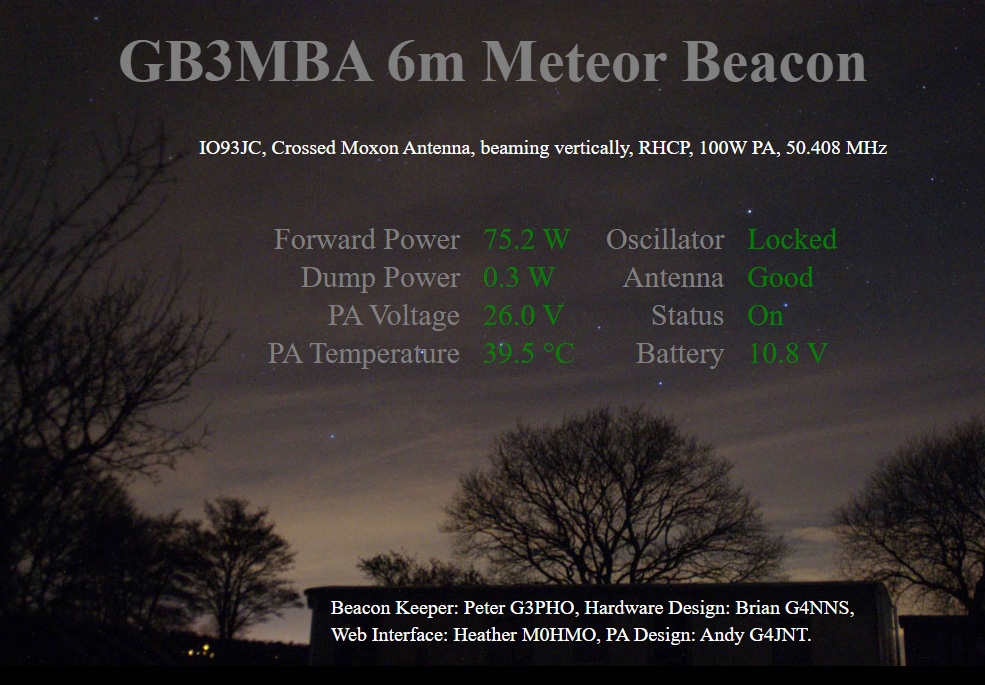
The beacon (see Figure 4), which is licenced by Ofcom, transmits a continuous carrier with about 75W, identifying every 10 minutes or so by A1A keying (as required by its licence). For its intended purpose any form of modulation is undesirable, as in Phase II of this project the carrier, which is generated by a precision GPS frequency reference, will be used to make precision Doppler measurements and modulation detracts from this.
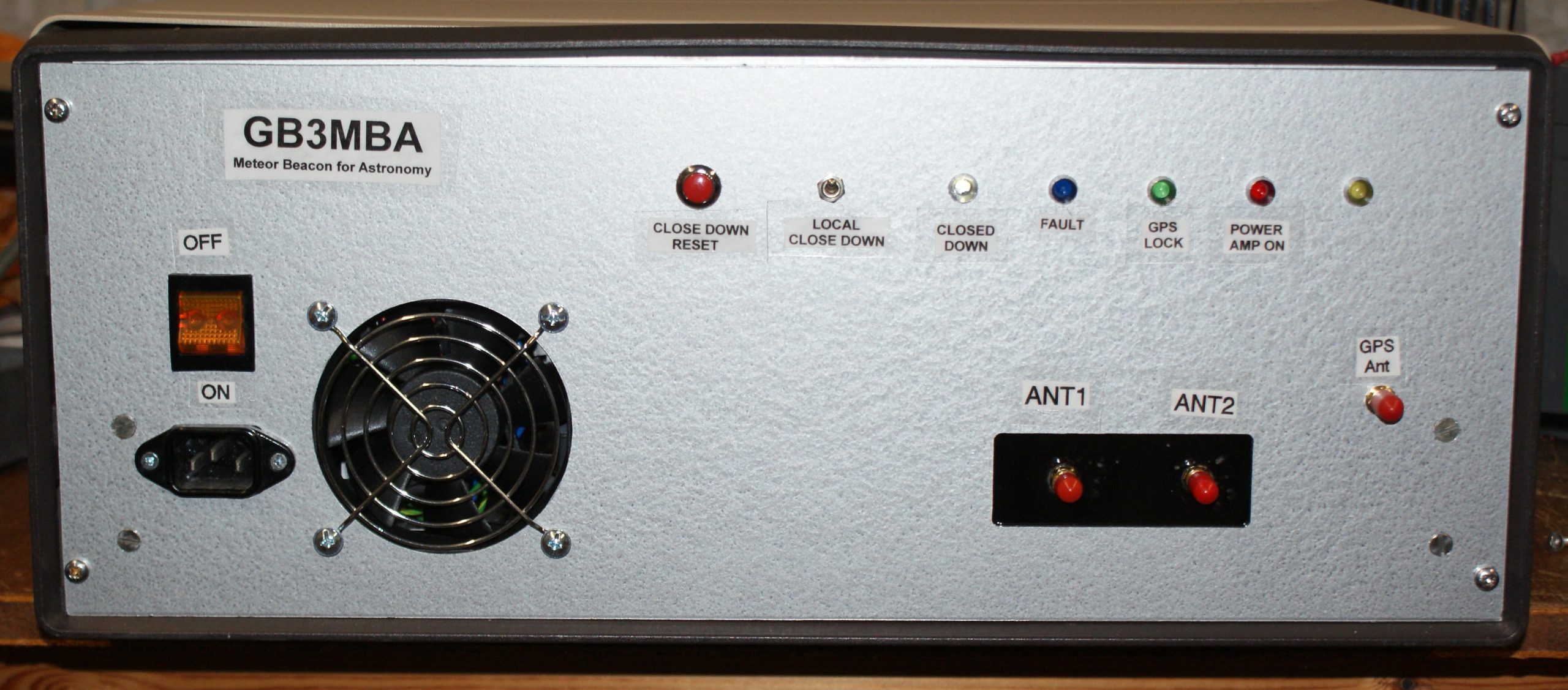
The output from the frequency reference passes through a filter and then drives the power amplifier (PA), which is rated for 100W continuous operation.5 A four-port hybrid splits the power to two outputs with a 90-degree phase shift. This is required to generate circular polarisation. Any imbalance between the antennas is fed to the fourth ‘dump’ port, which has a load monitored by a detector. If there is an antenna fault, the ‘dump power’ will increase, the transmitter will close down, and a fault condition will be reported. Circular polarisation is used as the head echoes from meteors behave like a wire antenna and are polarised. It reduces the loss due to potential misalignment of polarisation.
The beacon is monitored and controlled by a Raspberry Pi single-board computer, with interface circuits to monitor output power, dump power, PA voltage, PA temperature and back-up battery voltage. This battery ensures an orderly shut-down in the event of a power failure, but does not maintain beacon operation during a power cut. The Raspberry Pi also provides a web interface that can be viewed from the beacon website, at ukmeteorbeacon.org/status.1 (See Figure 6.)
The beacon has been built by volunteers from the amateur radio community, including the author (call sign G4NNS), Andy Talbot (G4JNT) who built the PA, and Chris Bryant (G3WIE) who made the four-port hybrid. Monitor, control and web interface software has been written by Heather Nickalls (M0HMO).
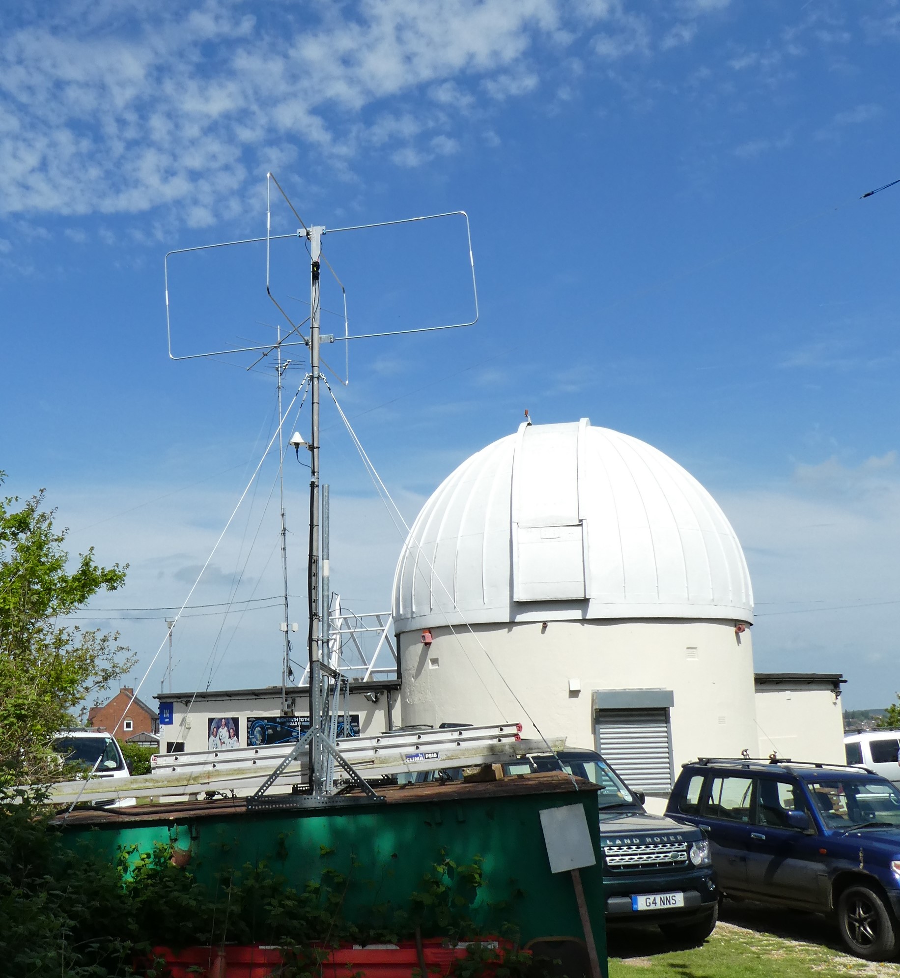
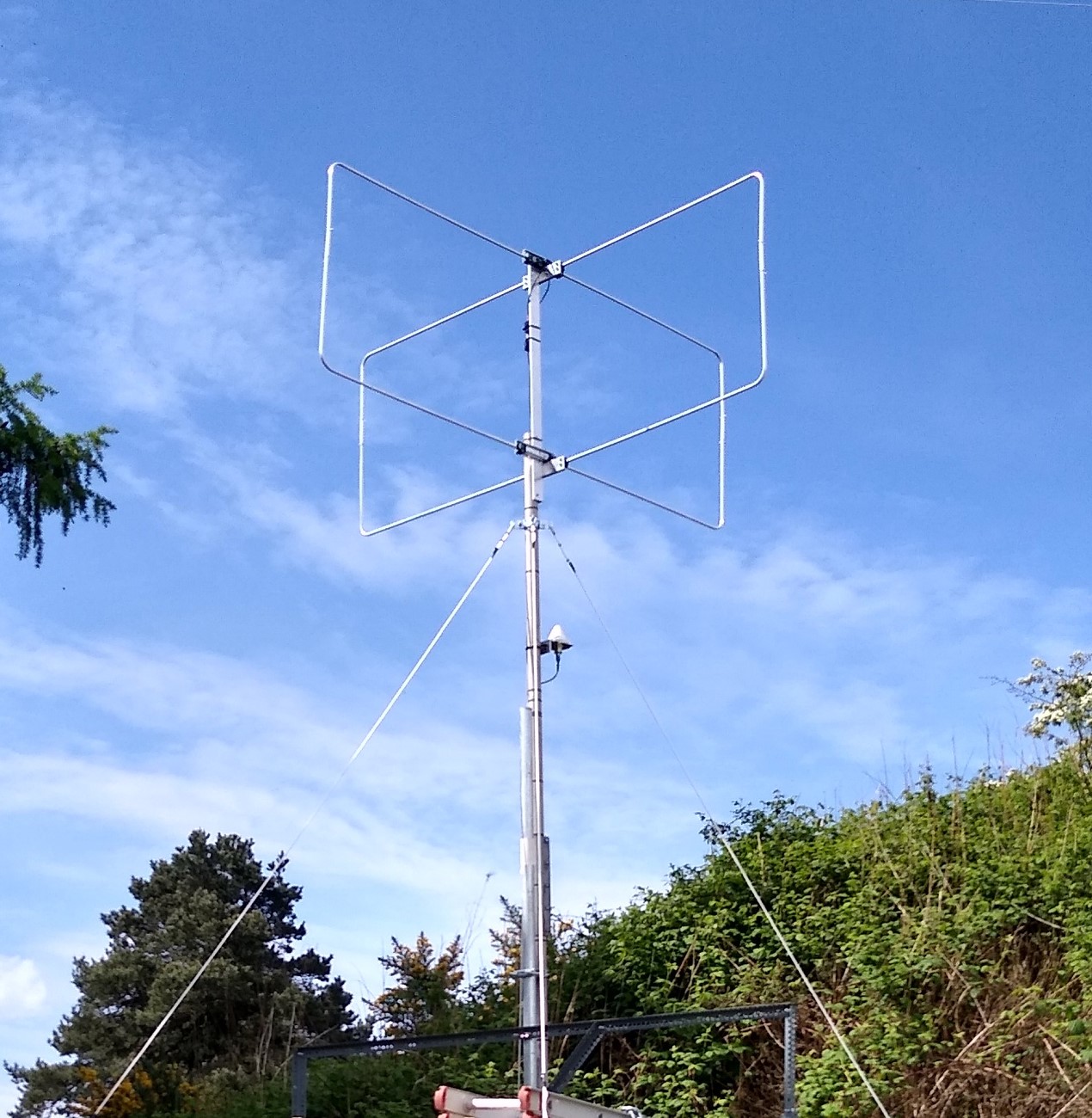
The transmit antenna
The transmit antenna consists of two Moxon antennas at right angles, fed with a 90-degree phase shift to generate right-hand circular polarisation. (See Figure 7.) The Moxon design was chosen as it is compact, with a very high front-to-back ratio and a broad beamwidth to illuminate the largest possible area above. Circular polarisation is used as head echoes are linearly polarised and would sometimes be cross-polarised with a linear transmit antenna, resulting in little or no echo. It is not considered necessary to use circular polarisation for receive, although this is an area that could benefit from further research.
Receivers
The best and most economical way of receiving and displaying radio echoes from meteors is to use a software-defined radio (SDR) connected to a PC. For my work so far, I use a FUNcube Dongle Pro Plus or RSP Duo together with SDR Console;8 I recommend this kind of configuration as a starting point. (See Figures 2 & 3.)
For those who already have one, a conventional receiver covering 50.408MHz can be used with an audio spectrum display such as Spectran.3 It is most convenient to display meteor echoes on a spectrum waterfall display.
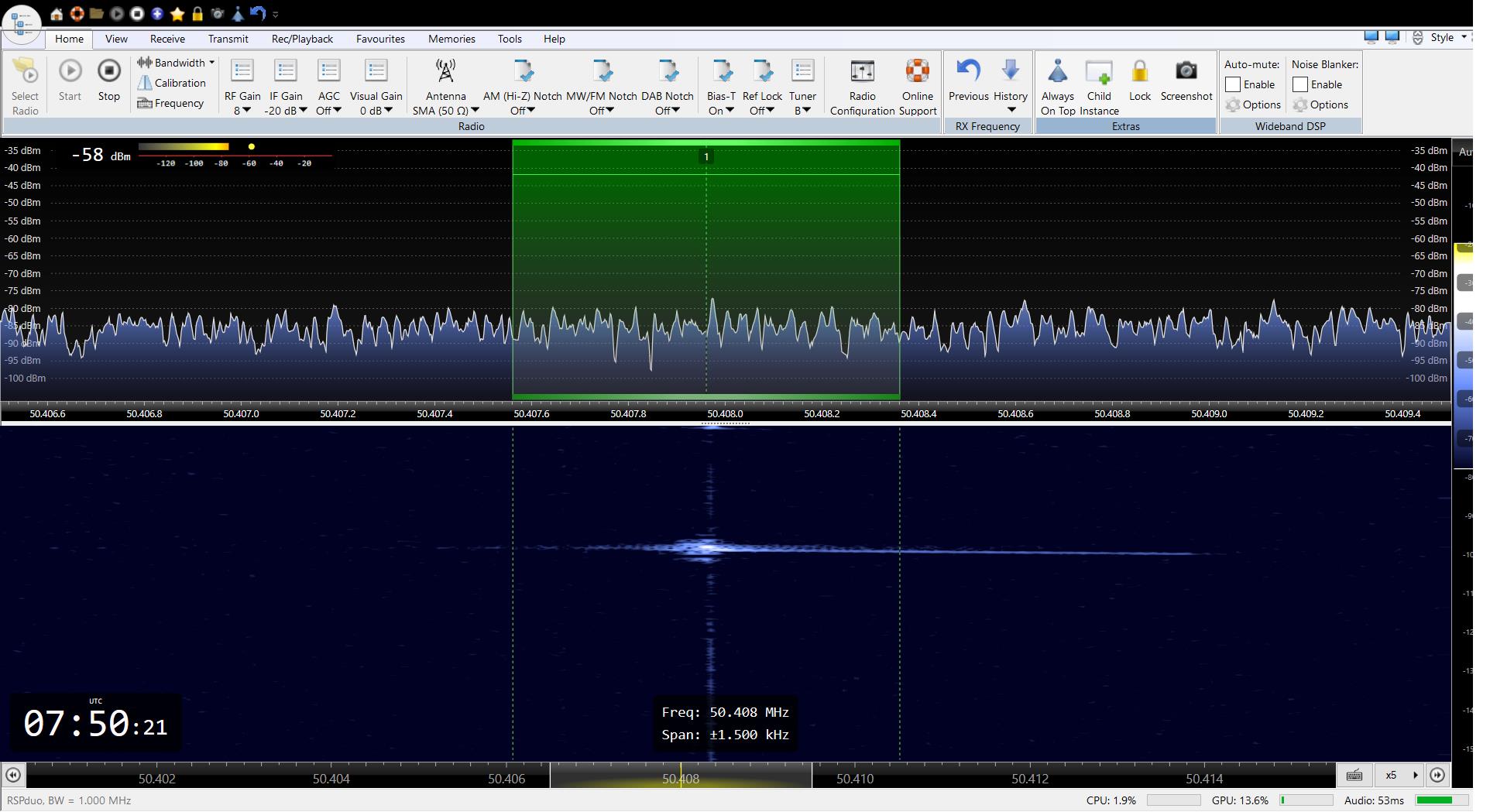
To monitor GB3MBA, only a small bandwidth (e.g., ±1.5kHz) centred on the transmit frequency of 50.408MHz is required. If you are thinking of establishing a receiver that can join the network proposed for Phase II of this project, you will need an SDR that can be locked to an external frequency reference, as precision Doppler measurements will be needed. The Phase II design team have yet to make a final decision on which SDR to use, but the RSPdx is under consideration at the time of writing.
Displaying meteor echoes
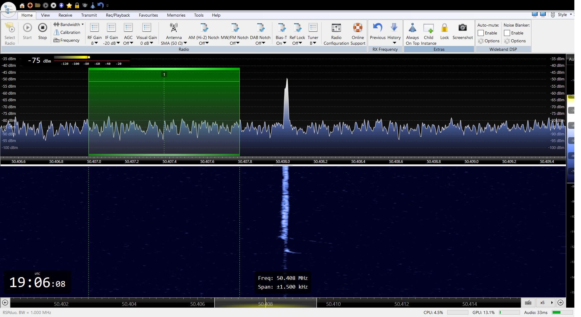
Figure 8 shows a meteor echo from BRAMS, as displayed by SDR Console. The upper portion of the display is a spectrogram showing amplitude vs. frequency; the wavy line represents the ‘noise floor’. The lower portion is a waterfall display and shares the frequency scale with the spectrogram above. The amplitude of the echo is represented by brightness on the waterfall and time flows downwards.
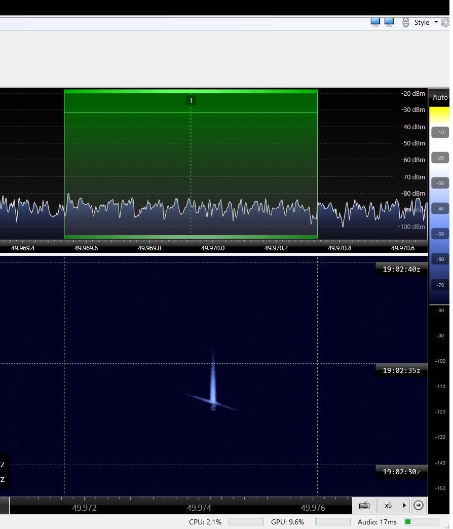
The head echo is the thin slanting line at the bottom of the bright trace on the waterfall. It shows the characteristic, rapidly changing Doppler shift as the meteor decelerates. In this example, the distance from beacon to meteor to receiver is reducing, as shown by positive shift.
The thicker, vertical line is the tail echo; little shift forms as the meteor passes through a region that becomes ionised. In this case, the meteor continues and the path from beacon via meteor to receiver increases, giving rise to a negative shift until it is completely burnt up or has cooled below the point where ionisation is sustained, and the head echo fades out. The region ionised by the passage of the meteor remains reflective to radio for a longer period of time. This is the tail echo.
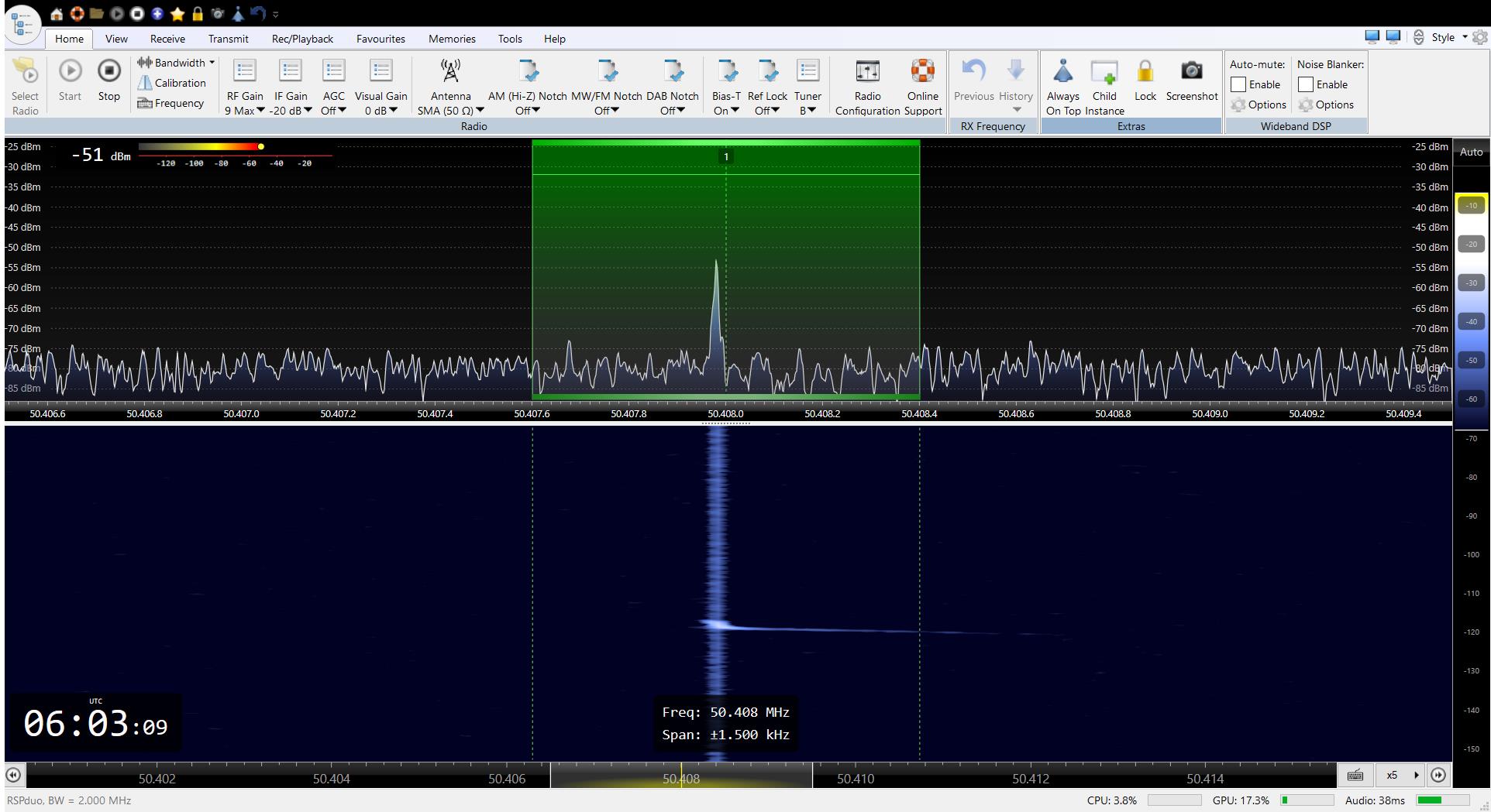
Radio echoes from meteors come in all sorts of shapes and sizes when viewed with a waterfall display. Figure 9 shows a particularly strong head echo, with a large positive Doppler shift as the meteor approaches and then a negative shift as it recedes.
It is the Doppler shift of events like this that we hope to use to calculate the location, trajectory and hence radiant (apparent origin) of meteors. The maximum shift observed, in this case, is almost 1,000Hz, which means the path from the beacon to the meteor and on to the receiver was reducing at almost 6,000m/s. The head echo ends with a negative shift of approximately 250Hz, so the path from the beacon via the meteor to the receiver was extending at about 1,500m/s.
Receive antennas
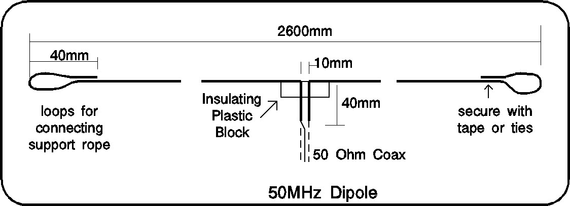
An objective of the project is to enable observations without the need for elaborate and expensive equipment, so that individuals and schools can create exciting STEM-based projects. A low-cost SDR with a PC and a simple wire antenna will, in many cases, provide a satisfactory way of observing meteor echoes. For those within a few hundred kilometres of the beacon, a dipole made from wire would be a good starting point. (See Figure 10.)
At greater distances, an antenna with gain and directivity will be helpful. For best results, it should be pointed towards the point 100km above the beacon. A Moxon antenna is proving a popular choice, due to its compact size and good directivity. UKRAA have a stock of a suitable Moxon antennas available to buy.6 Alternatively, you can make your own from wire and plastic waste pipe, as per the design referenced.7
Man-made noise
Man-made noise is the bane of radio astronomers everywhere, but particularly so in urban areas at 50MHz. So, it is well worth starting with a simple low-cost antenna such as a dipole to assess your local noise level, keeping the antenna in the clear and as far away from noise sources as possible.
A simple test to assess your local noise level is to measure the noise floor with the antenna connected and compare to when the antenna is replaced with a 50-ohm resistor. SDR Console shows the noise level at the upper left-hand side of the spectrum display (see Figure 3). If the noise floor increases by much more than 10dB when you connect the antenna, this indicates that you have a high local noise level and you may struggle to receive meteor echoes. First, try repositioning the antenna to find the quietest place for it. Even if you are close to the beacon, an antenna with directivity may help to null out local noise as you can point it upwards, away from the noise sources.
If your local noise level is too high to receive meteor echoes, all is not lost as in Phase II of this project is to deploy a number of receivers to radio-quiet locations and stream their data over the Internet, making them available to all via a central server.
Project Phase II
After some successful proof-of-concept tests, work is now starting on developing web-based receivers that can stream I/Q data via the Internet to a central server. The receivers will incorporate precision timing and frequency control so that events can be correlated and Doppler measurements from different directions used, to calculate the location of the event and the trajectory of the meteor.
I will be pleased to hear from anyone who would like to contribute relevant skills to the project.
References (external links)
2 GRAVES
4 BRAMS
5 Leo Bodnar mini frequency reference
6 UKRAA
https://britastro.org/wp-content/uploads/2022/10/Screenshot1-1.jpeg
https://britastro.org/wp-content/uploads/2022/10/Screenshot2-1.jpeg
https://britastro.org/wp-content/uploads/2022/10/Screenshot3-1.jpeg
https://britastro.org/wp-content/uploads/2022/10/Screenshot4-1.jpeg
| The British Astronomical Association supports amateur astronomers around the UK and the rest of the world. Find out more about the BAA or join us. |