Equatorial Platforms Part Two
Originally published as Equatorial Platforms Pt. 2, BAA Journal Vol. 132, No. 2, April 2022, E&T section, p85.
By Martin Lewis
Part One of this set of three articles explained how an equatorial platform worked and outlined the three main types, Poncet, Gee and d’Autume. In this follow-on part, I will discuss three variants based on the best aspects from these main types. All three discussed here are appropriate for heavier scopes due to their load-carrying ability and solidity and might be suitable for the competent amateur wishing to build their own equatorial tracking platform.
Equatorial platforms can be quite difficult to understand and unless you have a full grasp of the principles for the design you are building, you will struggle to be successful. I will try and convey these principles here rather than giving detailed plans to follow; space is too limited for the latter and if you understand the principles you can adapt the design to suit your particular preferences.
The three variants in order of increasing difficulty of manufacture are:
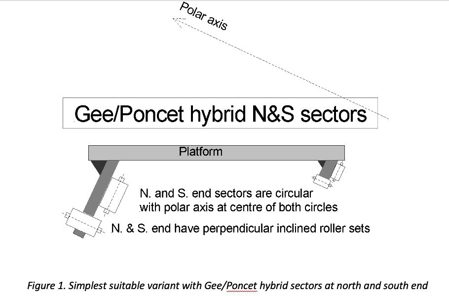
- Glee/Poncet hybrid at both north and south sectors (easiest)
- d’Autume at north end with Gee/Poncet hybrid at south end
- Vertical North Sector (VNS) with Gee/Poncet hybrid at south end (hardest)
You will see that all three chosen variants have the same arrangement at the south end and use a Gee/Poncet hybrid sector. In the basic Poncet or Gee platform, the south end normally uses a simple pivot. The basic d’Autume design, however, has a sector at the south end rather than a pivot, which is better. By having sectors at both ends and increasing the diameters of these sectors, it allows the polar axis to move upwards away from the platform. This allows you to position the polar axis so that it runs through the centre of gravity of the scope. This arrangement reduces torque on any drive roller used to rotate the whole platform, so making it less likely to slip when driving.
In the three designs outlined in this article, the benefits of the d’Autume south sector arrangement are exploited, but simplified – making the sector edge cylindrical in form rather than conical and using two sets of inclined rollers to increase stability and make it more suitable for a wider range of latitudes. The south sector really is a hybrid of the main north sectors for the Gee and the Poncet – using inclined rollers running on the edge from the Gee and rollers at 90° to the edge set but running against the sector face, as in the Poncet.
The first variant, shown in figure 1, uses essentially the same sector described above for the south end, but uses it at both ends of the platform – obviously with the sector at the north end being the larger diameter. The cylindrical faces of the sectors are significantly easier to make than the conical edges of the d’Autume. They can be shaped off the platform and fitted later, although there is the added complexity of the roller pairings to mount. Each sector needs two edge rollers, one on the east side and one on the west side. You can see a typical roller drive system below.
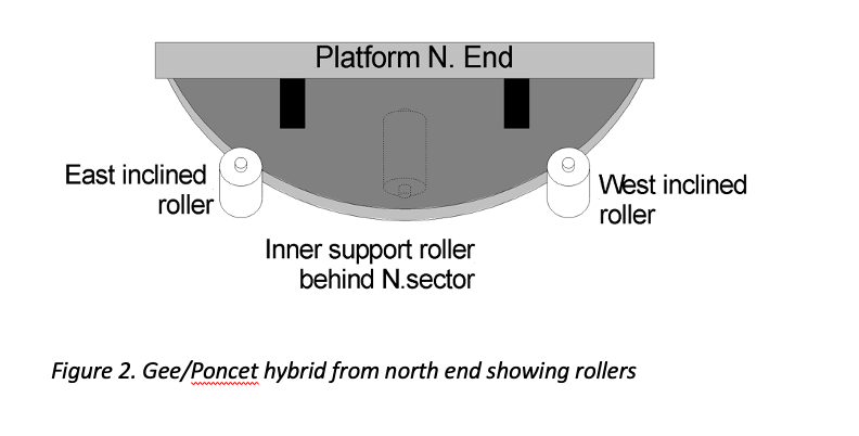
If the large north sector is in one continuous piece you only need one central rear face roller, as in Figure 2. If you make this north sector in two pieces, however, with separate north-east and north-west sections, then obviously extra face rollers will be needed.
Overall this is a good mechanical design but requires strong bracing, particularly for the larger angled north sector. There are also drive roller considerations which we will come onto in Part Three.
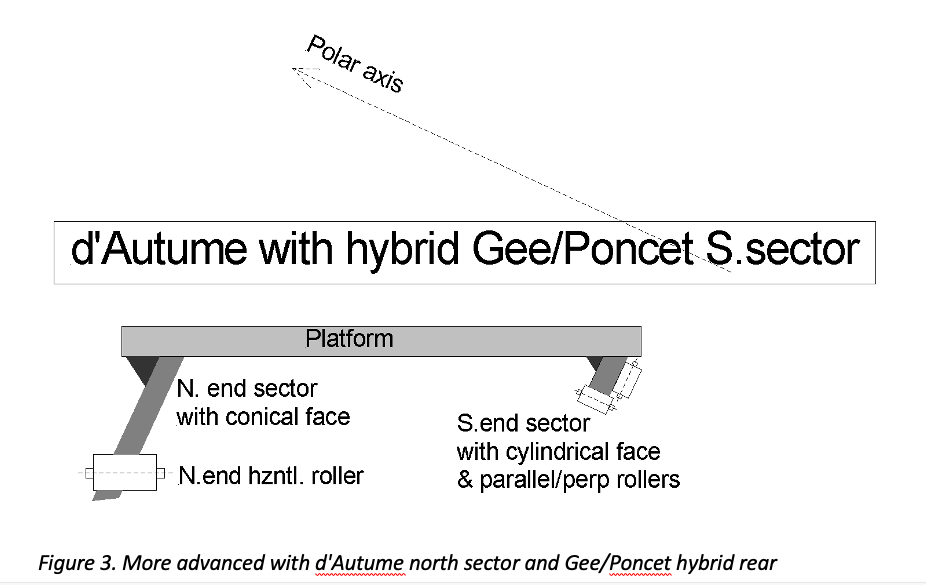
If you are feeling more adventurous then you might like to attempt the more ambitious d’Autume variant (figure 3). Here the north end rollers are horizontal and so support the edge without needing a second set of rollers to prevent lateral slippage. Horizontal rollers are easier to mount and can be driven more easily from a motor and gearbox; the downside is that such rollers require the sector face to form part of a cone. In addition, the vertex of that cone needs to be located on the polar axis, at the same height above the ground as the contact line of the rollers. This is best done by attaching the north sector to the platform, solidly mounting the whole platform onto a real temporary mechanical axis coincident with the polar axis, and then grinding the sector’s conical edges in situ, with something like a disc sander. This task really needs a workshop or garage set-up and some sort of CAD design capability to achieve the accuracy needed.
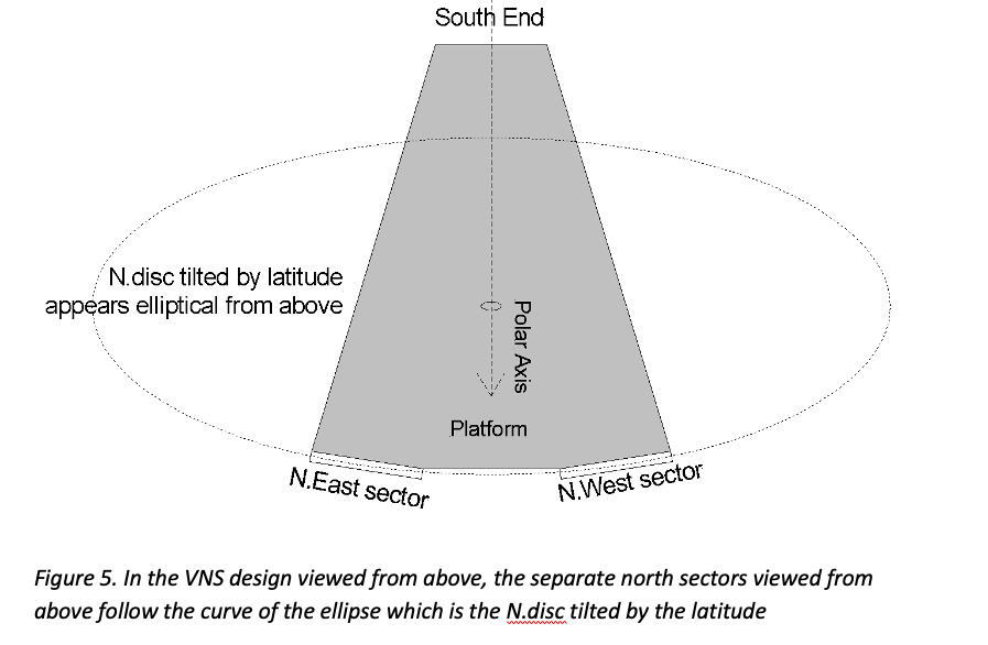
The most sophisticated variant of the three is shown in Figure 4. Here the north end is composed of two sectors rather than one, which are vertically set but angled to each other as you will see in the top-down view shown in figure 5. Again, as the north rollers are horizontal, the edges of the north sectors have to be conical in form with the cone’s vertex meeting the polar axis at the same height as the rollers’ contact faces. The same comments apply from the previous variant on how to achieve this.
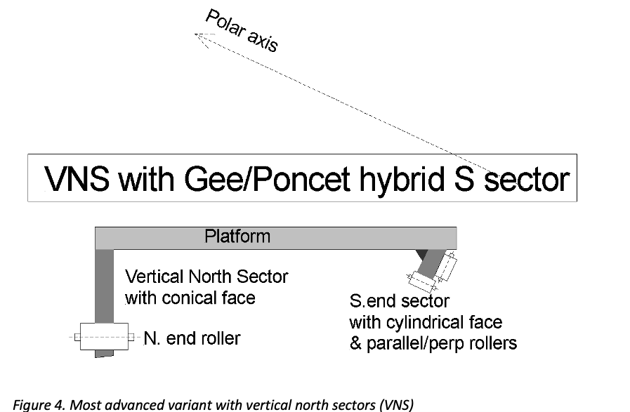
This VNS variant is the most compact and potentially the strongest of all the designs discussed here. With north sectors being vertically set, it does not need the strong bracing the other two variants do to support a sloped north sector.
Despite the advantages, this variant is probably the hardest of all to visualise and the most difficult to draw up prior to manufacture. It helps to know that over their lengths the bottom edges of each the north sector plates should follow the shape of the edges of a large circular disc centred on the polar axis and perpendicular to it (the N.disc in figure 1 of the previous article). Those edges after grinding should end up looking elliptical in shape when viewed from the north end and look like a diagonal line perpendicular to the polar axis when viewed from the side. Furthermore, in the design stage, you should position the sectors so that when viewed from above they also both approximate short sections of N.disc – which is also elliptical in shape from that perspective (see figure 5).
Part Three of these articles will discuss methods of driving the platform and aligning the polar axis.
| The British Astronomical Association supports amateur astronomers around the UK and the rest of the world. Find out more about the BAA or join us. |