Atmospheric Dispersion Part 2 – Orientation and Adjustment
Originally published as ‘Atmospheric dispersion, Part II: Orientation & adjustment’, BAA Journal Vol 131, No. 6, Dec 2021, E&T section, p348.
By Martin Lewis
In the first part of this article I described how commercially available atmospheric dispersion correctors (ADCs) are able to cancel out the prismatic effects of the atmosphere, which otherwise vertically separates the object’s different wavelengths of light. Atmospheric dispersion reduces resolution, especially at low altitude where the effect is worse – smearing the light into a vertical mini rainbow. This second part describes the correct positioning and adjustment of the ADC to best cancel out atmospheric dispersion.
Generally when imaging, Barlows or Powermates are used in the telescope to increase the image scale, better matching scope resolution to pixel size. Users ask where the ADC should be placed with respect to the Barlow. Placing it on the output side of the Barlow reduces the maximum angle of the cone of light entering the prisms and lessens aberrations, particularly astigmatism – which can be an issue for large amounts of correction. Having said this, due to other considerations, sometimes the ADC can only be placed before the Barlow. This is not all bad though, placing it further from the camera reduce the amount of prism correction needed, as the distance over which the correction acts is increased. This helps offset the increased aberration from the steeper light cone entering the device.
The atmosphere will always act to separate the light from an object in the vertical direction, with blue at the top and red at the bottom. The ADC needs to be to matched to the sky’s up/down orientation as seen through the focuser, so that the corrective dispersion introduced by the device’s prisms is opposite in direction to the dispersion caused by the sky. For refractors or SCTs with no diagonal, things are easy, as the vertical direction as seen through the focuser matches the human up/down frame of the observer and the ADC zero position, where the levers come together, just at the 3 o’clock position (or 9 o’clock – see later). Use a Newtonian, however, or use a diagonal and things get more complicated. This is because the vertical direction through the focuser does not now match the up/down direction of the observer. For my 222 mm alt-azimuth Dobsonian, for example, vertical is rotated 45° clockwise from the direction of the main tube axis.
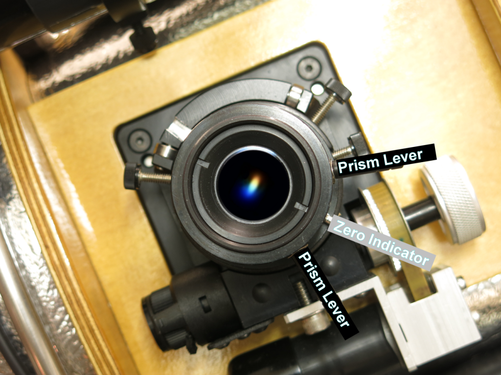
One simple method you can use to determine the external vertical direction is to pick a bright star close to your target and expand it hugely by throwing it out well out of focus. Placing a vertical ruler across the aperture of the telescope and looking through the eyepiece will show the vertical shadow across the expanded star. You can then orientate the ADC so the zero position is 90° around from this derived vertical direction. Most ADCs have their zero position to the right hand side, as viewed from the rear of the telescope, but some ADCs are lefties instead. The situation is further complicated by using a diagonal which can effectively invert the image making this more complex and requiring a rightie to be used as a leftie! If you get to the final adjustment stage and adjusting the ADC makes the dispersion worse rather than better then try rotating the ADC body 180°.
Once you’ve got ADC orientation correct, adjusting the amount of correction with the prism is relatively straightforward. The easiest method is to use a one-shot colour digital video camera and observe the image on a laptop screen via the common planetary imaging camera control program, Firecapture. Bring the two prism levers together at the zero position to start. Next find and focus on the planet, then change the exposure to by ~5x-10x to completely over-expose the planet. Next boost the colour saturation to maximum using the pre-processing feature. Doing these two things allows you to see the atmospheric dispersion effect as an obvious colour tinge at the edge of the over-exposed disc red on one side and blue on the other. Now the job is to move the two levers apart equally from the zero position to introduce a cancelling dispersion. The colour fringing should decrease as the prism dispersion increases and progressively cancelling the dispersion induced by the atmosphere. Eventually at some lever separation the colour tinge should disappear completely. If you find you can’t quite remove the colour fringing with any degree of lever separation, try rotating both levers both together clockwise or anti-clockwise to effectively fine tune the rotational orientation of the ADC.
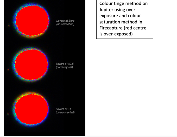
Firecapture has recently added this edge tinge method to its ADC tuning feature, boosting both the brightness and colour saturation temporarily just by ticking the check box. The feature also now blackens out the over-exposed planet’s centre just leaving the outer colour tinge. This helps improve the tuning accuracy considerably.
Do be aware that when you move the prism levers the planet will move in the field as the prisms divert the light. You may have recentre the object as you close in on the correct setting.
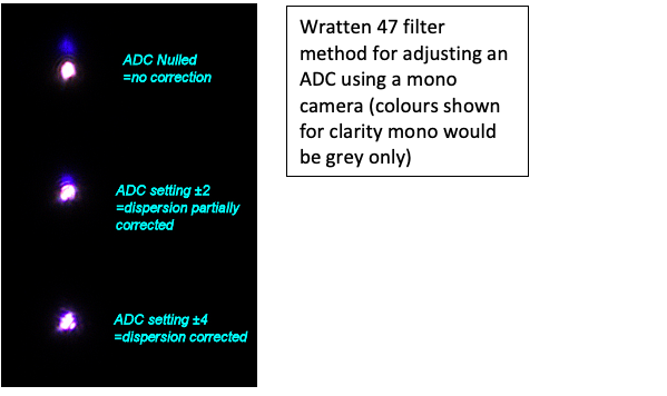
If you only have a mono camera you can try and set the ADC using an eyepiece to observe the colour fringing, but the eyepiece must be at the same focus position as the camera, otherwise the setting will be wrong. Focus with the camera first, then focus the eyepiece by moving it in and out of the holder without touching the focuser. Next adjust the ADC levers to attempt to remove the visible edge coloration before replacing the camera and imaging. Another method with a mono cameras to use Wratten47 filter with the camera and observe a star at the same altitude as your imaging target. The W47 filter will allow violet light through but also has a leak in the infrared. With the ADC at zero, atmospheric dispersion will cause the star to look double – with violet and IR images vertically separated. Moving the prism levers carefully apart should bring the two images closer together. At the correct ADC setting the infrared and violet images of the staff will merge into one. The ADC is then correctly set.
Setting an ADC correctly can be a fiddly process, but I promise after a few goes it does get much easier.
| The British Astronomical Association supports amateur astronomers around the UK and the rest of the world. Find out more about the BAA or join us. |