› Forums › Spectroscopy › ISIS flat field vertical gain correction tool
- This topic has 14 replies, 3 voices, and was last updated 6 years, 4 months ago by
 Dr Andrew Smith.
-
AuthorPosts
-
30 September 2019 at 4:04 pm #574411
 Robin LeadbeaterParticipant
Currently I do not use the option in ISIS to correct the vertical gain of the flat but David’s comments in the ISIS workshop video https://britastro.org/video/17273/19252 (at 59:10) prompted me to revisit this.
On the face of it there should be no need to worry about variations in the sensitivity of the spectrograph vertically along the slit as provided the spectrum is horizontal (as it should be) this has no effect on the shape of the spectrum. When subtracting the sky background however it is important that the intensity in the regions where the background is measured represents the intensity of the background where the spectrum is. This is where having a flat which accurately represents any variations in sensitivity along the slit could be useful, particularly with faint objects in light polluted skies where the background contribution can be large.
Ideally you would use a sky flat which would take into account all the effects in the optics including the telescope but that is not possible because of the Fraunhofer lines present in such a flat. Instead many spectrographs have a built in halogen lamp used to produce the flat. The problem is these systems can be rather crude and the illumination of the slit can be quite uneven along the slit so the tool in ISIS is there to get rid of this unevenness.
The tool however assumes that, in the absence of these lamp illumination issues, the sensitivity of the system (including the telescope) is otherwise uniform along the slit. I don’t know if anyone has checked if this is the case but I plan to take some sky flats and look at the profile along the slit compared with the profile using the lamp. Based on this, it should be possible to decide if it is better to use the vertical gain tool or not. Watch this space !
Robin
30 September 2019 at 6:03 pm #581421 Dr Andrew SmithParticipant
I remember looking at this some time ago. If you are going to do it I think you should apply a PRNU correction to remove fixed pattern noise first. At least then you are only removing, hopefully, low frequency vignetting and non uniform illumination .
In the end I used external tungsten flats with my LISA.
Regards Andrew
30 September 2019 at 9:12 pm #581422 Robin LeadbeaterParticipant
Hi Andrew,
I think for me the main problem the flat solves is getting rid of the ripples in the ATK428 camera response when used with the ALPY, that are otherwise difficult to accurately remove using an instrument response generated using a reference star, because of their rather close spacing
30 September 2019 at 10:02 pm #581423 Dr Andrew SmithParticipant
Hi Robin, I was not proposing not to use the flat just that if you used the vertical gain you would lose the pixel to pixel response variations. Maybe these are less important than the ripples.
As always experiment will reveal all!
I look forward to seeing what you find.
Regards Andrew
1 October 2019 at 12:41 am #581424 Robin LeadbeaterParticipant
Hi Andrew,
I think the algorithm just rescales each row the to the same mean level (on the assumption that the variation in mean from row to row is due to uneven illumination from the lamp or possibly variation in slit width) rather than averaging the columns so the pixel-pixel variation should still be there.
2 October 2019 at 12:23 am #581426 Robin LeadbeaterParticipant
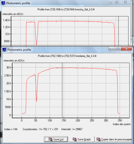
OK, for my setup the profile along the slit for sky flats is flat within ~+-2% but the internal lamp flat drops off by ~20% over the bottom third, presumably due to uneven lamp illumination, so unless this can be adjusted out somehow, it looks like the internal lamp flat would better match the true situation if the vertical gain tool is used. (The narrow dip on the left (bottom) edge is dirt on the slit)
 2 October 2019 at 10:10 am #581427
 Dr Andrew SmithParticipant
Interesting Robin, mirrors what I found. Can you do a similar plot after applying the correction?
By the way what software are you using to do the plots?
Thanks Andrew
2 October 2019 at 12:21 pm #581428 David BoydParticipant
Hi Robin,
The level of the background sky in my LISA images is very flat in the Y direction, much as you have found. The flat lamp image as recorded is not flat, probably due to the different light path from the lamp into the spectrograph. So I think applying the vertical gain correction results in a better flat correction.
David
2 October 2019 at 5:59 pm #581429 Robin LeadbeaterParticipant
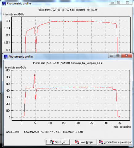
Here is the comparison with and without vertical gain correction.(The step on the right hand edge is outside the corrected area)

It flattens the profile as expected but note the artifact where the dust on the slit was, caused by the dispersion direction not being exactly aligned with the rows (tilt). This is an extreme example of course but there must always be some small errors across the whole flat if there is any tilt. (Note when measuring these column profiles accurately any slant/smile should be removed otherwise this can distort the profile measured in a vertical slice)
The profiles were produced using a rather obscure French program called Teleauto which I found when I started doing some photometry. (I forget the name of the author now)
http://www.teleauto.org/indexEn.php
It is obsolete now (only handles 16 bit images and struggles to run properly on win7) but it has some cool unusual features, particularly for its day (~15 years ago)
Cheers
Robin
2 October 2019 at 7:00 pm #581430 Dr Andrew SmithParticipant
Thanks Robin, so as long as you don’t have any significant real vignetting it seems to be the way to go.
I will give the software a miss.
Regards Andrew
2 October 2019 at 7:01 pm #581431 Dr Andrew SmithParticipant
Thanks Robin, so as long as you don’t have any significant real vignetting it seems to be the way to go.
I will give the software a miss.
Regards Andrew
3 October 2019 at 11:57 am #581432 Robin LeadbeaterParticipant
Hi Andrew, David
I have some reservations. The artifact from the dust line is worrying (There is a technical name for these isn’t there?). They wont be a problem in the sky background subtraction as they will average out but if they occur where the spectrum is binned they could distort the spectrum or at least give the wrong total flux. In fact a conventional flat would work correctly in this region, correcting the flux for the loss of light but the gain corrected flat would give the wrong flux even if the dispersion was exactly horizontal
Cheers
Robin
3 October 2019 at 7:43 pm #581434 Dr Andrew SmithParticipant
It looks as if it has differentiated the signal. Best to keep away from dust particles as if they fully block the slit not even a perfect flat can correct it if I remember the equations correctly.
Regards Andrew
3 October 2019 at 8:35 pm #581435 Robin LeadbeaterParticipant
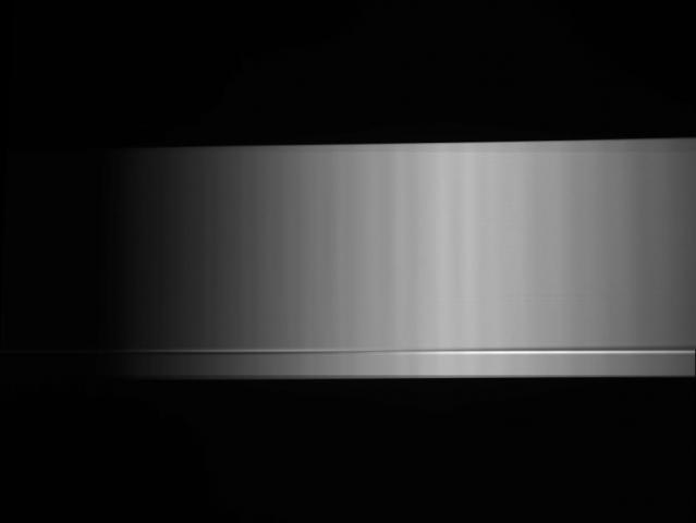
It does look a bit like that but no, it is just the result of normalising each row of a spectrum which is slightly tilted. Here is the whole “corrected” flat. The vertical gain correction algorithm only works correctly if the dispersion is exactly along the row direction.

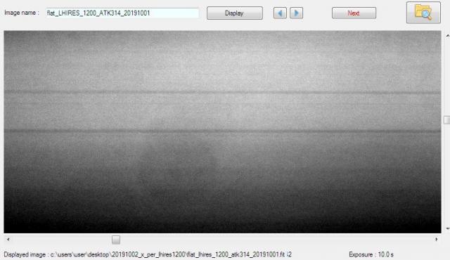
This is a severe obvious case but some variations along the slit are much more subtle. For example these in a highly stretched LHIRES flat image from last night are down at the 1% level and are in the region where I take spectra. They are not anything to be too concerned about as an uncorrected flat should work ok to divide them out but not if they are tilted and I apply the vertical gain correction
 4 October 2019 at 4:39 pm #581438
 Dr Andrew SmithParticipant
Hi Robin, it confirms, I think, it is better to put the effort into having hight quality data and calibration frames than to try and fix it in software.
That’s why I used an external flat source with my LISA.
Regards Andrew
-
AuthorPosts
- You must be logged in to reply to this topic.
