› Forums › Spectroscopy › LASER experiments and spectral calibration
- This topic has 21 replies, 6 voices, and was last updated 6 years, 4 months ago by
 Derek Robson.
-
AuthorPosts
-
13 November 2019 at 12:28 am #574443
 Derek RobsonParticipant
I had meant to start this topic but set the text on one of the images on my profile page, which may not get seen compared to the new topics. Therefore I re-posted the text here. The images are still in my profile page, which you would have to visit to see them.
I wondered if anyone had used LASERs as a method of using its known wavelength to calibrate the x axis of astronomical spectra.
I’m carrying out some experiments with coloured LASERs to look at how close they can be used to calibrate the wavelengths of light in the spectra of astronomical objects such as stars, meteors. There are two series of experiments going. I. With a Watec 902 H2S camera mounted outside, with a diffraction grating of 500 lines/mm. 2. With an unmodified Canon DSLR 1100D and standard lens 18-55 mm set at 18 mm, with the same grating material.
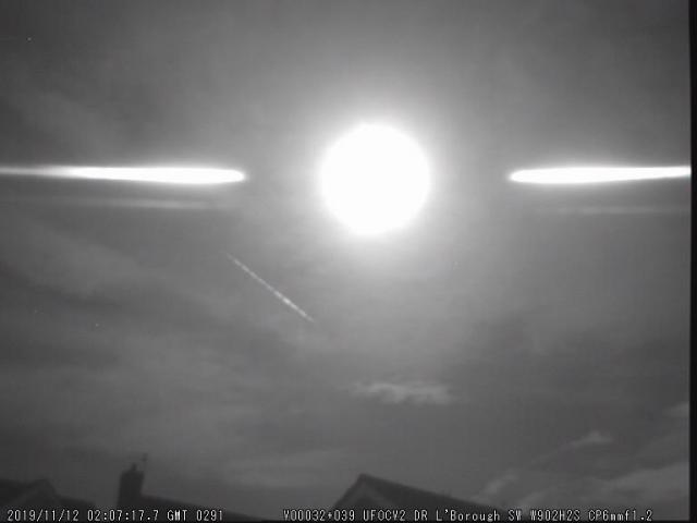
During taking images of Vega spectra, I also pointed the LASER at Vega and energised it momentarily. On the direct hits, the images show the first order diffraction spectrum (n = -1 and +1) of the LASER (of known wavelength, e.g. green 532 +/- 10 nm) was diffracted and landed at the right place on the spectrum of Vega – I was “in the green”. So it showed the experiment worked and I thought it demonstrated the physics of diffraction in a colourful way. Vega itself is used as a spectral calibration star. I have also done this with Sirius, as shown. The LASERs on the black and white images are being used to calibrate the spectra of meteors for that camera. I have uploaded an image of a bright meteor, with its spectrum shown as white lines on the right side. The black and white images on the rooftop showing small white dots are the zero and first/second order spectra of the LASERs used as calibrations. Quite a nice science project.
13 November 2019 at 2:45 pm #581589 Robin LeadbeaterParticipant
I am also trying to figure out if (and if so why) the distance along the laser beam changes the measured dispersion. The images showing reflections in the window suggest it does, though they will be much nearer than the typical beam distance of course. Can you see any loss of parallelism (is this a word?) between the zero order and dispersed beams?
Cheers
Robin
13 November 2019 at 2:48 pm #581588Robin LeadbeaterParticipantHi Derek,
A neat idea. You could use it to check how constant the dispersion is across the field. (A potential issue with objective gratings and wide angle lenses due to distortions)
Does anyone know if the wavelength is stable for a given pointer? (If so its wavelength could be calibrated) or does it vary eg with current and temperature? I have some cheap red green blue pointers. I might run some stability tests using the ALPY or LHIRES
Cheers
Robin
13 November 2019 at 4:13 pm #581590 Dr Andrew SmithParticipant
Interesting idea. I have taken the spectra of a red laser using an echelle spectrometer. This clearly shows that it has multiple modes. I will try a d find it.
The big boys use lasercombs but rather out of my price and capability range. While goggling them I came across an Amazon advert for cheap lasercombs but alas they were for hair.
Regards Andrew
14 November 2019 at 3:50 am #581594Derek RobsonParticipantI haven’t processed the images in BASS, ISIS or RSpec yet (I don’t have RSpec but maybe get it). Just by eye, looking at the green, red and blue LASERs, the first order diffraction falls into that colour along a spectrum of Vega or Sirius. I read recently of one of the astro spectroscopists who did the opposite of what I did. He measured the wavelength of a green laser with a spectrophotometer using a calibration lamp. For a green laser he used, he was spot on to within 0.1 nm of the stated wavelength, and that result was probably well within the experimental error of the determination. I don’t know how much they vary in quality between products. I’ve read that many are reliable in wavelength and bandwidth. Isn’t the process required to stimulate the radiation the same i.e. it is a specific atomic de-excitation that causes the light, and it’s energy (frequency or wavelength) is well-defined by chemistry and physics of the energy levels of the elements used in the LASER. Green and blue tend to be of one wavelength, whereas red ones fall into more than one category of wavelength, depending on which one it is. That was a problem I encountered with my red LASER, I didn’t know which it was, but it was a standard collimation LASER. For the purposes of identifying elements in meteor spectra, I think they are still likely to do the job because some element lines can be identified relative to each other, even if the calibration is out a bit or a lot.
14 November 2019 at 4:08 am #581595Derek RobsonParticipantThe beams look like they are not parallel between zero and 1st order. But I thought that’s the way the physics worked – the light is diffracted through an angle relative to the incident light. I’ve done a series of repeatability tests by firing LASERs at roof tops and aerials (in the dead of night) and will be looking at the spread of the distances from the zero order. But this is on dots, not the beams. I’m looking at the target as the source of the LASER light coming back to the sensor. Some images on the wide angle lens show the beams at angles. But we know even parallel roads will join together in the distance (perspective). I’m measuring the position of the diffracted dot relative to the zero order dot. That should show if there is any non linearity in the wavelength range I guess. Another problem is, the diffraction gratings are plastic, so they are not rigid, and can bend, causing curved spectra (curvature along the wavelength axis). But despite that variation, I hope that will be insignificant and not interfere significantly, or at all, with identifying elements.
14 November 2019 at 11:31 pm #581602Derek RobsonParticipantI slept on that one and awoke with an optics headache, hmmmm. “why) the distance along the laser beam changes the measured dispersion”. I’m not sure now. I was thinking about what is it that we are seeing when looking at a LASER beam. I have a vague memory that you can’t or shouldnt be able to see them, except if the beam is blocked by something. I think that the visible beams are due to reflections from illuminated particles in the air. Am I right in assuming that the first order “beams” that we see, are not really there in the air (unlike the pointer beam)? That is, the first order beams are constructed from an infinitesimal number of diffractions from the same number of sources of illumination along the primary beam going outwards to the chimney pot? And the light is diffracted after the grating, so doesn’t happen in the air outside, but rather, in the camera? On the parallelism, I started to think what the LASER beam would look like in the following two situations a) the beam is normal to and horizontal to the grating and sensor. I’d expect to see a dot on left and on right side, with dispersion distance “A”. But if we tilt the LASER to say 45 degrees upward (pointing to a roof top), how would the diffracted dots appear in the spectrum? (the LASER would be hitting the grating at 45 degrees tilt. Would the dots be dispersed by a distance B which was smaller or larger than A? or should A = B always (whatever the distance; but might differ with tilt)? Is that what you meant? It has me baffled. Could geometry solve it?
14 November 2019 at 11:38 pm #581603Dr Andrew SmithParticipantDerek, can you draw a diagram if what you think is going on? I can’t follow the verbal description.
Regards Andrew
14 November 2019 at 11:41 pm #581604Derek RobsonParticipantYes, I’ll draw a diagram and post it. Just bear with me.
16 November 2019 at 1:18 am #581605 Steve KnightParticipant
The red laser pointers you see are laser diodes, wavelength not particularly well characterised, it varies with operating temperature, ~0.25 nm / deg. I would recommend a green laser, these are normally diode pumped solid state lasers. Wavelength always 532nm, determined by energy levels in Neodymium rather than band gaps in a semiconductor. Blue lasers are diode lasers as well so again wavelength not well characterised. An old style red gas laser would be good, these are Helium Neon lasers, wavelength always 632.8nm.
17 November 2019 at 1:59 pm #581608 Hugh AllenParticipant
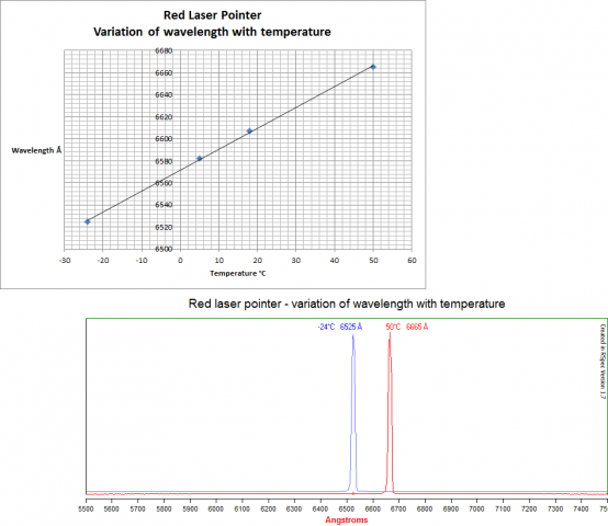 Hi Derek / Steve,
A few years ago I used my Alpy 600 to look at the variation of wavelength of my red laser pointer with temperature, using my fridge/freezer and kitchen oven with a mercury thermometer. The results are attached, giving a variation of 0.19nm/deg
Cheers
Hugh
17 November 2019 at 7:32 pm #581609Steve KnightParticipantHugh, I’m just impressed that you had actually measured it. Not surprised though, just impressed! Also very relieved that my guesstimate was not so far off!
18 November 2019 at 3:20 am #581610Derek RobsonParticipantHi Hugh
That’s a great piece of experimentation. It’s interesting to see what looks like a linear relationship. I wonder if this is a kinetic effect in the diode mechanism (Arrhenius equation etc)? compared to the transition in neodymium for the green light that Steve mentioned (maybe the transition in neodymium is not sensitive to temperature changes?). It’s all good because this discussion has led me to standardising on using the green LASER. In fact (out of curiosity) I may calibrate the blue and red LASERs using the green one as the primary standard. For meteor spectra surveys, it will be easy to make a green LASER calibration frame/s at the start or end of a batch of exposures [better at the start because of the dew formation later]. But I think once done and I have a value of the number of pixels the green LASER is dispersed in the first order diffraction, as long as the equipment stays the same, lens, focal length, grating, do you think the calibration will no longer be necessary ? Oh, I think I need to follow up with Robin’s comments on distance. I will need to do some exposures with various objects at different distances painted with the LASER. Robin, do you think it’s important to know the actual distances? A problem I have is, I don’t know the distances – they are just roof tops, aerials etc. Is there a way to work out their distances?
18 November 2019 at 8:39 am #581611 Dr Paul LeylandParticipant
With the red laser I suspect it’s thermal expansion of the cavity which changes the resonant frequency. The LED is a broadband emitter but constructive interference occurs only when the cavity is an integral number of wavelengths. Change the length and the resonant wavelength changes.
The Nd transition is at a frequency governed by an electronic transition involving a 4f orbital. Those orbitals are largely isolated from their chemical and thermal surroundings so the transition is very much narrow band which doesn’t change greatly with temperature. The pumping diode is a broadband source but that doesn’t matter as long as it emits strongly enough at the laser frequency.
In a previous life I used to play with a tunable laser — a dye laser pumped by a fixed frequency argon-ion laser in that instance. It was tuned by changing the length of the cavity.
18 November 2019 at 9:49 pm #581614Robin LeadbeaterParticipantHi Derek
>But I think once done and I have a value of the number of pixels the green LASER is dispersed in the first order diffraction, as long as the equipment stays the same, lens, focal length, grating, do you think the calibration will no longer be necessary ? Oh, I think I need to follow up with Robin’s comments on distance. I will need to do some exposures with various objects at different distances painted with the LASER. Robin, do you think it’s important to know the actual distances? A problem I have is, I don’t know the distances – they are just roof tops, aerials etc. Is there a way to work out their distances?
I can’t add much I am afraid as expected the dispersion to be a constant of the setup so the effect of the distance to the source came as a surprise to me ! Perhaps it only becomes significant as the focal length of the lens becomes a significant fraction of the distance. I think I would start with something close, a couple of metres away say compared with a few tens of metres to get a feel for the magnitude of the effect.
Cheers
Robin
19 November 2019 at 12:36 am #581615Derek RobsonParticipant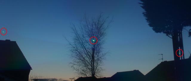

 Thanks Robin, will do. After the E&I meet, because it’s easy to set away APT running short 6s exposures during the night when dark enough, I was able to time and fire the green 532nm LASER and move around various targets whilst I could hear APT finish exposure, start exposure…..etc, so managed to build up a few shots to work with. Some will be squiggled, other’s nice and clean dots. I should be able to measure the dispersion in pixels (or mm on screen) and see what we get. I have a suspicion that I’m going to get slightly different dispersion distances for n = +1 and n = -1, possibly because of the grating, being plastic, it’s not completely flat but is curving. Depending on where the dot occurs, if it’s on a part that’s more curved, relative to the opposite side of the zero order image, we might get discrepancies there. All nice experimentation. could make decent experiments for school projects.19 November 2019 at 12:17 pm #581616Robin LeadbeaterParticipant
Hi Derek,
>I have a suspicion that I’m going to get slightly different dispersion distances for n = +1 and n = -1, possibly because of the grating, being plastic, it’s not completely flat but is curving. Depending on where the dot occurs, if it’s on a part that’s more curved, relative to the opposite side of the zero order image, we might get discrepancies there.
That would be really strange, I think. The light from the laser dot on the distant object illuminates the full grating (just like a star illuminates the full aperture if the telescope.) The grating then produces a number of beams at different angles according to the spectrum order, which are then brought to focus by the lens. Distortions in the grating could blur the spectrum because the effective line spacing varies across the grating but I don’t understand how it could affect the +- orders differently. If you are seeing different dispersions in +- orders I suspect It would be more likely to be due to aberrations in the lens (eg barrel/pincushion type distortions for example.
Cheers
Robin
19 November 2019 at 8:25 pm #581617Derek RobsonParticipantHi Robin
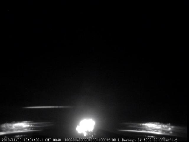
Thanks for that, I will keep that in mind when checking. I have been zooming in on screen at times and making a mental qualitative note of separations, then scrolling along to the other side, and noting that distance. There may have been occasions where I’ve zoomed without realising, then thought, that distance looks different. I’ll find out later on in the quantitative analysis. I’m glad you made that point about lens distortion because, on my Watec camera [which is not these colour results] the lens shows some stars as blurred on left side, in focus in middle, and blurred again on right side but not as bad as on the left. (6mm lens). Spectra on that camera do show differences between + and – orders relative to zero order; and because the grating is just taped on the outside of the CCTV box, and is slightly curved across the front, and having seen the intense spectrum of the moon, that’s where I noticed the curvature, and got the idea it was due to curved grating. The pictures selected (the moon upper and a firework, lower) show the curvature more pronounced if the object is lower down (as in the case of the firework) – but the dispersion looks roughly symmetrical. Note, on the curved part, I try to make a linear pixel measurement as a best estimate, although I’m not sure whether I should be measuring the dispersion along the curve [or flattening that curve in e.g. BASS before dispersion is measured. But I know flattening can introduce errors, so I don’t want to go there. I’d rather take measurements when the dispersion is flat]
So it’s good to know that’s lens distortion. On the colour work, the lens is Canon 1100D with std 18-55 mm lens, set at 18 mm (and, on occasions, different f number (3.5, 8, 11, 22), stopping down because the sky was so bright. Would different f number affect/conceal those lens distortions you mention?
19 November 2019 at 9:24 pm #581618Robin LeadbeaterParticipantThat does look rather like pincushion distortion
https://en.wikipedia.org/wiki/Distortion_(optics)#Radial_distortion
(In stellar spectra, atmospheric refraction can also bend the spectrum but this cannot be the cause here)
Lens distortions will also distort the spectrum along the dispersion direction as well as bending the spectrum. The DSLR lens is probably better in this respect than the CCTV lens. What does the image look like without the grating eg eg does the roof line look curved as you move from top to bottom of the frame ?
If the lens is distorting the image significantly that will make precise calibration difficult. Once defined you could correct the distortion first in software first which should straighten everything out and linearise the dispersion. I don’t have any direct experience of handling this with meteors and wide angle lenses though. Perhaps Bill Ward has come across it and has some ideas on how to deal with it ?
Cheers
Robin
19 November 2019 at 11:28 pm #581620Derek RobsonParticipantThanks Robin
Because the diffraction grating is only a recent addition in the last year, I have images through the CCTV camera without the grating, so I can hunt out a direct comparison frame. Bear with me and I’ll grab an image. I might be able to stack the two to see if any changes are obvious, but I might have to alter B, C, gamma, invert etc, to provide images that can easily be seen together as an overlay.
kind regards
Derek
-
AuthorPosts
- You must be logged in to reply to this topic.