Equatorial Platforms Part Three
Originally published as Equatorial Platforms Pt. 3, BAA Journal Vol. 132, No. 3, June 2022, E&T section, p151.
By Martin Lewis
Part One in this set of articles explained how an equatorial platform works and outlined the three main types of platform – Poncet, Gee and d’Autume. Part Two discussed three variants based on the best aspects from these main types, all of which would be appropriate for heavier scopes due to their higher load-carrying ability. This final article describes driving the platform and aligning it, so that items placed on are able to correctly follow the rotation of the celestial sphere.
To enable the equatorial platform to track properly, in addition to it being well-designed and well-built, the platform must also be aligned so that its polar axis is aligned parallel with the Earth’s axis. In addition, for the 60-80mins that the platform can track, the rate of rotation of the platform about this polar axis must match sidereal rate.
A well-designed platform should be relatively easy to align when used at its home latitude. It is a good idea to design things so the moveable platform top is parallel with the platform base when at the mid-point in its movement range. If this criteria is met, then adjustment of the polar axis in altitude just entails ensuring that the baseboard is horizontal. This can be done using adjustable feet at the three corners of the platform and two separate bubble-levels – one to set the tilt of the base E-W, and a second to set the tilt N-S.
Setting the azimuth orientation is a bit trickier, but once correct you can mark a reference line on the floor, parallel to one of the base edges and this makes it much easier next time round. A good way of determining the azimuth orientation, is to use the drift method. With a telescope mounted on the platform, point it at a star within 30 mins of the meridian and within ±5° of the celestial equator and see if that star moves progressively North or South in the field of view:
⦁ If the star drifts South, the platform’s polar axis is pointing too far East
⦁ If the star drifts North, the platform’s polar axis is pointing too far West
Adjust the platform base iteratively to minimise the drift, marking a line on the floor to align to next time.
Driving the platform usually involves driving one of the North sector rollers at a rotational speed where anything placed on the aligned platform tracks at sidereal rate. The required rate of rotation needs to be calculated from the diameter of the drive roller and the distance of the sector face from the polar axis. A crucial aspect of driving is that the friction between the roller and the sector needs to be high so that there is no slippage here. I have found that a brass strip on the sector which bears against a stainless driven roller works very well for this application.
The vertical north sector (VNS) design of equatorial platform, discussed towards the end of article two, is a bit more trouble to make compared to simpler designs. Even so, it has a number of advantages as far as driving is concerned. One plus, is that the loading bears down vertically onto a horizontal roller and this maximises the frictional force – minimising slippage issues. A horizontal roller is easier to drive too as the drive mechanism can be arranged horizontally on the bottom board rather than having to be a some specific angle to the base.
Driving a platform is usually accomplished by using a stepper motor, synchronous motor or DC servo motor, at the heart of the drive system. The advantage with these sorts of motors is that the rate of rotation of these can be accurately adjusted to match sidereal rate. The motor will almost certainly need to be reduced in speed with a gearbox, but due consideration will need to be given to reducing backlash in the final drive, as even small amounts of can cause issues in use and poor tracking. One tried-and-tested method to help reduce backlash, is to use a worm and wheel arrangement on the final drive shaft, with the worm having a sprung load on it to ensure intimate contact with the wheel.
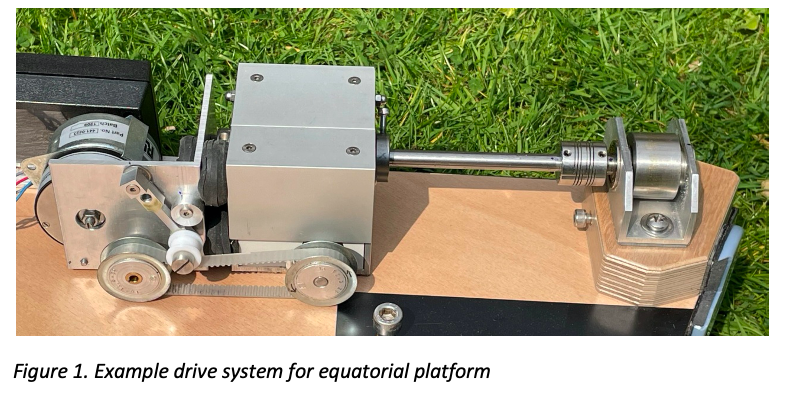
You can see a typical roller drive system below. From left to right we have – 250rpm synchronous motor and 250:1 gearbox, tensioned drive micro-tooth belt, 40:1 worm and wheel gearbox, final drive shaft into flexible coupler and finally the 30mm driven stainless roller which the VNS sector rests on (with an effective diameter of 1056mm).
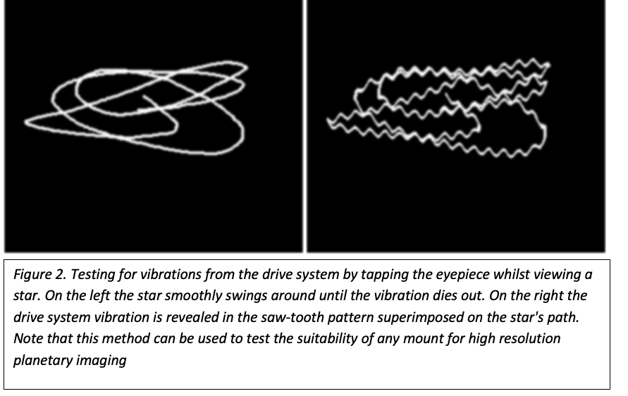
One key aspect of your drive system, if you are intending to use your platform for high resolution planetary imaging, is the amount of vibration it produces. Vibration from the drive system coupled to the telescope can noticeably compromise resolution. Often you won’t be able to see any sign of this through the eyepiece at high power, but a simple test involving tapping the eyepiece when viewing a star reveals its presence, as described in the figure below.
Reducing any motor vibration can be a difficult task although the use of wood in the platform helps. Synchronous motors have benefits over stepper motors here. I chose a low-vibration synchronous record deck motor, under-driving it at 90v instead of 110v, to further improve matters. With a synchronous motor you can also improve vibration levels by optimising the value of the capacitor that introduces the lag between the two drive phases. A big help in addressing vibration issues is mechanical isolation of the motor and damping techniques. In my set-up, shown in figure 1, the motor bracket is mounted to the worm/wheel gearbox via three sets of vibration-absorbing Sorbothane pads, compressed by ~25%. I also use a flexible drive belt for the transmission of the drive.
I do hope this set of articles inspires you to have a go at building your own equatorial platform, or at least helps you appreciate them a bit better.
| The British Astronomical Association supports amateur astronomers around the UK and the rest of the world. Find out more about the BAA or join us. |