› Forums › Spectroscopy › LHires experience – and some issues…
- This topic has 44 replies, 6 voices, and was last updated 7 years, 11 months ago by
 Mr Jack Martin.
-
AuthorPosts
-
8 August 2018 at 10:42 am #579833
 Kevin GurneyParticipant
Hi Robin
“Images of the star on the slit can be deceiving if the star is over exposed as the overspill looks worse than it is.”
Yes – I try and stretch the guide image so that I see only the central core of the star. Without doing this I do see a bloated disc [Incidentally, I am using Hyperion Prism as my frame-and-focus/guiding/ software now… I like it]
With my 35mu slit, Isis reports a resolution of around 15K. This compares with the 23mu slit R of just over 17K – about a 10% loss. Inspection shows that the fine atmospheric lines are not quite as deep but I’m not worried about that..
By the way, do you know how Isis calculates R? It seems to do it from the image/spectrum and not from parameters as such
cheers
Kevin
8 August 2018 at 10:55 am #579834Kevin GurneyParticipantHi Robi
sorry – I am out of sequence with my replies – you note “A wide spectrum, even if it does not affect the total flux is not ideal as you have to sum more rows, introducing more noise from the camera and sky background.”
I think thats what I found (and optimal binning doesnt play nicely).
It looks like you dont see the progressive vertical widening as you move the mirror (so the image goes down the sensor)?
I think Andy saw this?
Looking at the geometry, the narrow spectrum appears to be when there are smaller angles involved in the projection between mirror, grating and sensor. So might you expect some spreading as you increase these angles? My spectrum when at the top of the image is quite narrow… I have not tried loosening the screws on the grating holder – it sounded scary 🙂 But maybe I should try and re-tighten to get a feel for how this works
Kevin
8 August 2018 at 11:04 am #579835Kevin GurneyParticipantAnd for comparison here is my spectrum image in the top half..
It doesnt seem quite as good as yours – I may well have a look at the grating clamp screws…
Kevin
8 August 2018 at 12:07 pm #579836 Robin LeadbeaterParticipant
Hi Kevin,
I will reply to all posts here to avoid having to chase up and down the thread. (I have to say I don’t like this type of forum layout. I much prefer the more common layout like Stargazerslounge etc which are linear and you can quote)
Reply to #8
>(i) The spectrum gets wider (more height in Y-axis) as it goes down the sensor.
Yes to me this is unexpected but we need confirmation if it is normal. No clear skies here but I will dig out my artificial star or perhaps replace the slit for a hole and see what I get. I think we need to check this first before adjusting anything else.
>(ii) As well as this, the overall integrated flux gets bigger – an increase of around 50% from the two extremes explored here. I am assuming the final Isis image has removed the background and so the flux is signal, rather than background+signal. (You might expect total flux to increase just because its a bigger area…)No the total flux should stay the same. (The light from the star is just being spread over more rows). The flux may be changing as the mirror vignettes the return beam
>(iii) However, the spectrum is not so good in the larger-flux, lower-in-image version. In particular, it doest work well with the optimal binning optionOptimum binning selects particular rows to maximise signal/noise. For flux measurements, turn off optimal binning (and just set the binning zone to just include the full height of the spectrum (stretch the image to see the full extent) and subtract the background setting the background zones away from the spectrum above and below
Reply to #14
>By the way, do you know how Isis calculates R? It seems to do it from the image/spectrum and not from parameters as such.
I think it calculates it from the lamp spectrum. It can give variable results though. I prefer to measured the FWHM directly off the lamp spectrum. R = wavelength/lamp line FWHM
Reply to #23
>I have not tried loosening the screws on the grating holder – it sounded scary 🙂 But maybe I should try and re-tighten to get a feel for how this works
I recommend we clarify the widening with mirror position first before touching the grating.
Cheers
Robin
8 August 2018 at 2:00 pm #579837 Andy WilsonKeymaster
I think Robin has covered a lot of stuff really well. I will add a few more thoughts from my experience, taking Robin’s lead by replying to all of the points in one post.
Reply to #8
>(i) The spectrum gets wider (more height in Y-axis) as it goes down the sensor
>(ii) As well as this, the overall integrated flux gets bigger – an increase of around 50% from the two extremes explored here.
>(iii) However, the spectrum is not so good in the larger-flux
I wonder if these are all related. As I understand it you are moving the spectrum down the slit, taking a series of images. I am not sure you would expect the same quality of spectrum near the top of the slit, in the middle, and at the bottom of the slit. I suspect, but could be wrong, that the narrow vertical height of the spectrum might be due to some of the light being cut off by either missing the mirror or otherwise not following a path that successfully reaches the sensor. Hence, you see more flux with a wider height, which does not look as good, because this is how the spectrum naturally looks when all the light successfully passes through the spectrograph. I remember looking at this with my Lhires III. I also experimented with different mirror positions and at first thought great I am getting a nice tight spectrum. Only later did I look at the throughput and then realise I was getting less photons.
If you can get a nice spectrum in narrow vertical height with the same signal, then that is of course ideal. However, a spectrum spread in height of 10 or even 20 pixels is not necessarily a major problem. The geometric corrections should sort out the spectrum lines so they are nice and vertical, so you won’t loose much in resolution when the signal from different rows is combined. Also spreading the signal over a few pixels can be a good thing as then you have not got the problem of a single bad pixel or cosmic ray hit ruining a region of the spectrum.
Another way to investigate how the throughput changes with vertical position of the star on the slit is to take a sky spectrum at twilight, or possibly even daytime. It is like a flat, though not a flat you could use as it will be the solar spectrum. For this type of investigation the flat lamp may not be as good as it may not illuminate the slit evenly. The idea is by looking at the change in intensity with height, it will give you an idea of where to position your star for maximum throughput. Remembering the stellar spectrum does have vertical height, so this is not perfect, but it will give you a good feel for where maximum light passing through the slit to reach the CCD. Of course you can do this by positioning the star at different positions on the slit, but this gives a quick way to look at the whole slit.
On another topic related topic. I always try to position the star at about the same position in vertical height on the spectrograph CCD, as this minimises differences between spectra. Even though a flat field should remove most variations, I do everything I can to make create a repeatable accurate spectrum. When carrying out response or flux calibration, this means the light from both the reference and target stars following the same path through the spectrograph, and illuminate the same CCD pixels.
Grating Holder
I found the grating holding was pinching my grating a little too tightly, and this was distorting the grating and so the spectrum. I loosed the holder, and then re-tightened it so the grating was held firmly in place. I saw a noticeable improvement in my spectrum, but it still had a vertical height of 10-20 pixels.
Cheers,
Andy
8 August 2018 at 8:49 pm #579839Robin LeadbeaterParticipantI have converted over to the latest guider mirror setup and I made some tests today using the internal flat lamp and a pinhole in place of the slit (actually a piece of foil with a slit in it overlaid at right angles over the middle of the original slit.) This effectively simulates an on axis star in the spectrograph, though the effective focal ratio may not be correct.
I first checked that the crossed slits were central in the guider image so the slit and my guider image should be centralised on axis. (Hopefully the guider image coma will be minimum at this position too when I make a test on the sky)
I then recorded flat and calibration lamp spectra at H alpha 1/3 from top,middle and 1/3 from bottom of the camera field (having previously focused the calibration lamp lines for best focus.)
The first thing to note is the instruction to set the spectrum at 1/3 (from top or bottom) is rather meaningless as the actual position will depend on the size of the sensor. (I have an ATIK 314 with 6.45um pixels so moving 1/3 of the field equates to moving ~2.2mm)
I found that there was no change in total flux or spectrum resolution for all three positions. (though because the effective focal ratio of the flat lamp may not match that of the scope, potential vignetting will need to be checked using a real star)
I did indeed find that the thickness of the spectrum increases when moving the spectrum from top1/3 to bottom1/3. In this case approximately doubling in width (FWHM) from ~ 50um to ~100um or 8-16 pixels (The actual size of the pinhole in this direction is no known as it was just scored in the foil) This seems less than you were quoting Kevin, though perhaps you have a larger sensor/smaller pixels ?
I also made the same measurements on the zero order image with similar results, though the height of the zero order image was a bit less than that of the spectrum, (~2/3) possibly due to the anamorphic factor which makes the diffracted image narrower in the dispersion direction but wider at right angles to it.
Robin
8 August 2018 at 9:04 pm #579840Robin LeadbeaterParticipantAndy’s comments started me wondering about this. There are two ways to move the spectrum vertical position in the camera field. You can adjust the spectrograph mirror or you can move the star along the slit. You commented, Kevin that the slit position and the sweet spot did not correspond to the centre of the guider field. (They should do when everything is correct.) I wonder if because of this, where you are placing the star is off the spectrograph axis, exaggerating the widening effect in the spectrum.
Robin
9 August 2018 at 9:45 am #579841Kevin GurneyParticipantHi again
I’ll combine my replies to Robin and Andy here…
Andy said “ As I understand it you are moving the spectrum down the slit,”
No – I am changing the angle of the main mirror using the set screw on the bottom. I try and use a central slit position at all times. As you swing the mirror back and forth, you get the images I showed.
On grating holder… Today I tried the screws – they were as tight as they could be… Mmm.. (Thanks to Andy for posting the diagram of which screws to adjust on http://www.spectro-aras.com/forum/viewtopic.php?f=8&t=997&start=20)
I took this opportunity to adjust the grating for uniform image placement over wavelength range. It wasnt bad before – a change of about 10% of vertical sensor size in going from Ha++ to zero-order image – but I got it down to 5%. They were tiny adjustments…To do this I used the Shelyak recommended hi-tech approach – piece of card with a gap in it, placed over the mirror slit – but it works for this. At the end, I just cinched the screws tight and didn’t drive them all the way home.
Robin noted that the total flux should stay constant. Logically it should, so let me explain what I am measuring. I am taking the final summed image from Isis, then just doing a windowed stats measuremnt of the spectrum image. But I think Andy also reported a change in total flux with this kind of manipulation…?
I am waiting for abreak in the clouds to try all this with a real star… It could be my slightly mis-oriented prism (and/or some overtightening of the grating clamp) was causing some artefactual thing here…
Kevin
9 August 2018 at 10:32 am #579842Kevin GurneyParticipantI managed an hour outside last night and tested the mod on the guide mirror – much better! There is now a ‘sweet spot’ in the middle of the guide image (rather than at one edge) and I think the image as a whole looks generally a bit better. Recall I tilted the guide mirror forward using a washer between the mirror mount and the frame. I should get in touch with Francois I think…
I know that early versions had three degrees of freedom on the guide mirror (two tilt and back-and-forth). The reduction to one with the piston design has thrown some of the ‘baby out with the bathwater’ in my view..
Incidentally – adjusting the main mirror angle still has the same effect as described in this thread (move image across sensor and change its height) – my tweaking the grating has made no substantive difference.
Kevin
9 August 2018 at 10:37 am #579843Kevin GurneyParticipantHi Robin
To clarify this – the effect I am talking about is brought about by moving the main mirror on its axis using the set screw in the base. In spit of my guiding difficulties (now resolved! – see below) I still had the star in the centre of the slit. I simply had to have the slit well off to one side in my guide image to get the centre into the sweet spot zone
Kevin
9 August 2018 at 11:55 am #579844Kevin GurneyParticipant…. (contd) but (to clarify again) I can get a good spectrum in the top half of the image. My question is whether what I see is ‘normal behavior’ under mirror movement
Maybe a face-to-face at the late September meeting if we are all going?
Kevin
9 August 2018 at 1:36 pm #579845 Tony RoddaParticipant
Hi Robin, Are those not the same as Relco 480s? That’s what I’m using and their appear identical.
Regards T
9 August 2018 at 1:37 pm #579846Tony RoddaParticipantT
9 August 2018 at 2:45 pm #579848Robin LeadbeaterParticipant> I know that early versions had three degrees of freedom on the guide mirror (two tilt and back-and-forth). The reduction to one with the piston design has thrown some of the ‘baby out with the bathwater’ in my view..
I am thinking that too. I can see why it was done as It was easy to get into a mess with the old tip/tilt setup but the new setup depends on that wall of the spectrograph being very accurately square which cannot be guaranteed with the type of case construction used. Having reviewed what I posted on that ARAS thread, I am not convinced my alignment is quite as good as originally. There is not enough room for the old mechanism now though with the the calibration lamp mechanism.
9 August 2018 at 3:05 pm #579849Robin LeadbeaterParticipantYep the good old Relco 480 (but possibly gold plated given the price !) To be fair though, I believe there is a lot of variability so Shelyak select the better ones and discard the rest. Starlight Xpress use it in their spectrograph too. A great discovery by Richard Walker who should be on commission! My first tests with it in the LHIRES are here
http://www.spectro-aras.com/forum/viewtopic.php?f=8&t=606&hilit=relco+starter#p2380
Robin
9 August 2018 at 4:35 pm #579850Andy WilsonKeymasterHi Kevin,
Good to hear you are making progress in the right direction.
I misunderstood the way you were moving the spectrum. I too experimented with moving the mirror, though this was 2-3 years ago and I cannot remember all the details. I think I originally saw an improvement in the appearance / reduced height of the spectrum with the mirror at one extreme. I later realised I was getting less flux and so I think I was cutting off some of the light, or missing some of the light in that position.
I will be at the Observers Workshop in September.
Cheers,
Andy
9 August 2018 at 4:58 pm #579851Kevin GurneyParticipant… and the fit of the piston shaft into the retainer is not as tight as it might be, so some play there….
Anyway. I’ll see what Francois says…
In the meantime, I have some split washers of just the right thickness if anyone wants one 🙂
Kevin
9 August 2018 at 6:25 pm #579852 Steve CuthbertParticipant
Hi guys
Reading Kevin’s post and replies with much interest I‘m struck by the problems he seems to be having and judging by the replies it seems acceptable and perhaps the norm that these are to be expected. My reasoning being that given the price of the LHires it seems reasonable to expect it practically to work ‘out of the box’ or have I just got my Alpy 600 head on ;-))
Regards
Steve
9 August 2018 at 8:27 pm #579854Andy WilsonKeymasterHi Steve,
I found that my Lhires III worked out of the box, other than initial setup like focusing and finding the micrometer setting to view the H-alpha line. It is a more complex instrument than an Alpy, so there are more things to adjust and it may not be the best place to start out in spectroscopy.
I managed to get some decent results on my first night, helped by the fact that I had previously been using an L200 which has a lot of similarities with the Lhires III. I did see improvement from my first observations to later ones as I tweaked the setup and learned how to get the most out of the spectrograph. It is a continual journey, and I am sure in a few years I will be getting even better results.
To show you what I mean, below are some observations from my first light with my Lhires III. First a spectrum profile of zeta Cas.
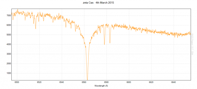
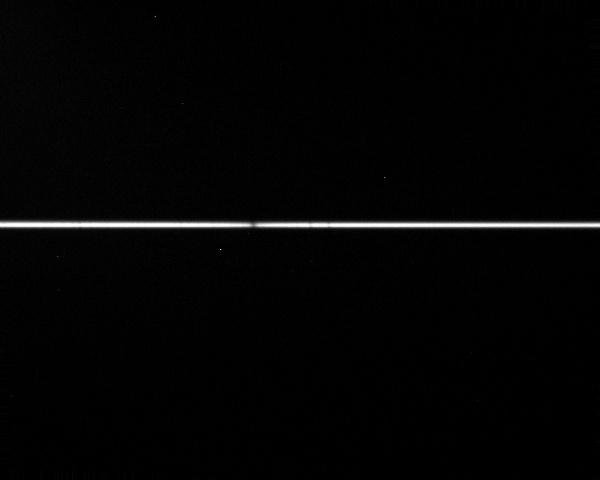
Here is one of the spectrum images.
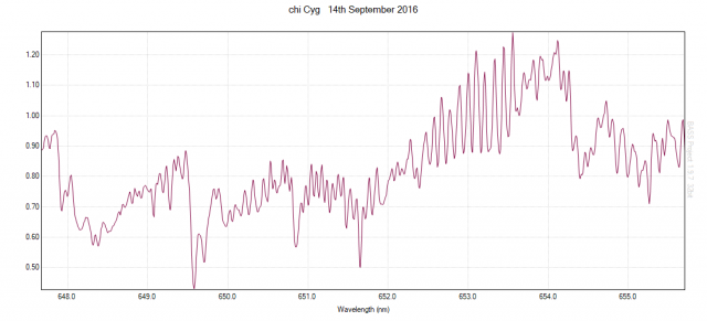
Then about 18 months later here is a spectrum of chi Cyg.
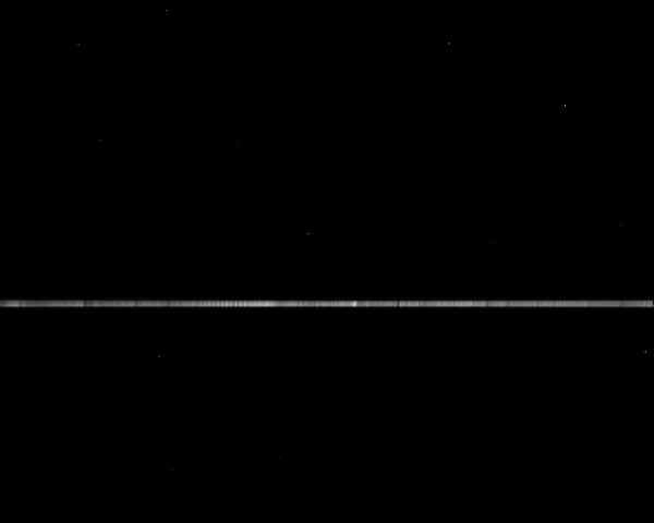
And the underlying combined spectrum images.
Cheers,
Andy
9 August 2018 at 11:06 pm #579855Steve CuthbertParticipantHi Andy
Nice first nights spectra!. I realise these are complex instruments but with a new expensive instrument I would balk at having to “ tilt the whole mirror assembly forward slightly which was effected using a washer on the top screw “!. Just my twopennuth .
Steve
-
AuthorPosts
- You must be logged in to reply to this topic.