› Forums › Spectroscopy › MIZAR
- This topic has 12 replies, 3 voices, and was last updated 7 years, 10 months ago by
 Peter Taylor.
-
AuthorPosts
-
19 March 2018 at 10:21 am #573980
 Peter TaylorParticipant
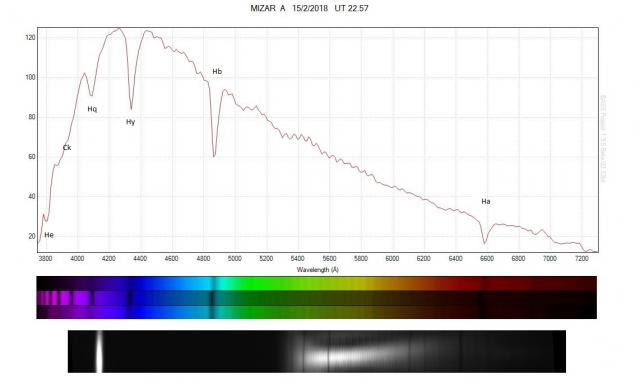
Hi All, Got this with my 200SA and a LOADSTAR CCD, scope WO ZS80IIED, prosiest in BASS, 10 X 10second images.
peter

Attachments:
19 March 2018 at 6:14 pm #579236 Andy WilsonKeymaster
Hi Peter,
It looks like you are off to a good start. The hydrogen Balmer lines are clearly visible so everything must be working. I note there is a bit of a wiggle in the spectrum from about 5300 to 5900 Angstroms. From the regularity in the spacing I wonder if this might be an interference effect that I have heard of with some cameras. There could be a hint of it at other wavelengths too.
Cheers,
Andy
20 March 2018 at 10:07 am #579238 Peter TaylorParticipant
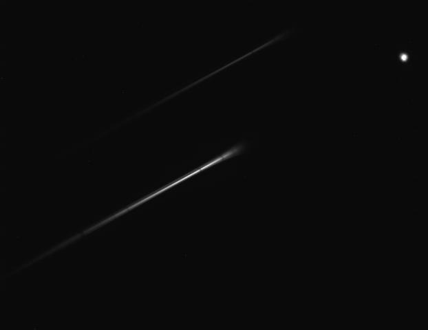
Hi Andy If it is camera can I get it out or do I put up with it, image was about 45 degrees can it be from altering it.
peter
20 March 2018 at 8:59 pm #579239 Robin LeadbeaterParticipant
Hi Peter,
I suspect the ripples could be because the spectrum is at an angle. (The camera response can also cause ripples but they tend to be broader than what we are seeing here.)
You can orientate the grating with the camera off the scope. Look at the sensor through the grating and rotate the grating until the images of the sensor produced by the grating all line up.
Cheers
Robin
EDIT – Peter, not John. (senior moment!)
21 March 2018 at 9:07 am #579243 Andy WilsonKeymaster
Hi Peter,
As Robin has pointed out, there may be a very easy fix to the ripples, which is simply to orient things such that the spectrum falls along the camera chip length ways.
Cheers,
Andy
25 March 2018 at 3:19 pm #579253 Peter TaylorParticipant
I have the star analyser and camera chip lined up as you suggest thy are in one unit I put in scoop eyepeas holder so they are set OK but image is to long do I move camera nearer or away from star analyser to shorten image.
peter
25 March 2018 at 6:51 pm #579254 Robin LeadbeaterParticipant
Hi Peter,
Moving the grating closer to the camera shortens the length of the spectrum. You can calculate the effect using the on line calculator.
http://www.patonhawksley.co.uk/calculator/
You may find that you cannot get the SA200 close enough to the camera sensor when mounted on the camera nosepiece. The SA200 is designed to be used close to the sensor, for example in a filter wheel, not on a camera nosepiece. The best model to use for this application is probably the SA100. You can use the calculator to decide which model is best
Robin
25 March 2018 at 7:13 pm #579255 Robin LeadbeaterParticipant
The best distance of the SA200 from your camera sensor for your setup would be about 30mm but you can use up to 40mm and still fit the spectrum and zero order horizontally. See the attached calculator output. Note that this camera has large pixels for your short focal length which means your images are probably under sampled (~3 arcsec/pixel) This can also give problems with ripples in the spectrum as the thickness of the spectrum may be narrower than a single row of pixels.
Robin
25 March 2018 at 11:11 pm #579256 Peter TaylorParticipant
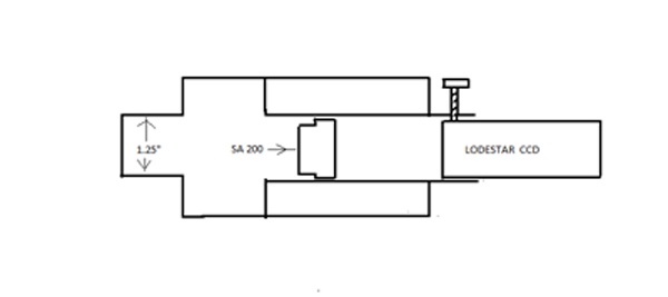
Robin I think we have got across I have made a unit to hold the SA200 and my Lodestar CCD so it is just a mater of putting it in the ZS80IIED and all is the same every time all I need to do is focus, from the Grating to CCD Calculator I get 17mm to 30mm I have it set at 23.5mm so the CCD needs to be nearer the SA200, to get image all on screen I have to tern it 45 degrees.
peter
 26 March 2018 at 11:22 am #579257
 Robin LeadbeaterParticipant
Hi Peter,
If the distance from grating to sensor is 23.5 mm you should be able to easily fit the useful part of the spectrum (0 to 7000A) horizontally across the camera field (If this is a mono camera without an IR blocking filter the spectrum will continue further into the IR up to perhaps 9000A and there will be a faint overlapping second order spectrum beyond that but the part we need is just 0-7000A.)
Cheers
Robin
26 March 2018 at 4:11 pm #579259 Peter TaylorParticipant
Hi Robin, My Starlight Xpress Lodestar CCD is a mono, so I can let the end of the spectrum be out of the image, I will try it at 17mm to see what happens, image is what I get in Maxim DL 5 Pro at 23.5mm it is obviously all on the Lodestar CCD chip.
peter
 26 March 2018 at 8:18 pm #579260
 Robin LeadbeaterParticipant
Hi Peter,
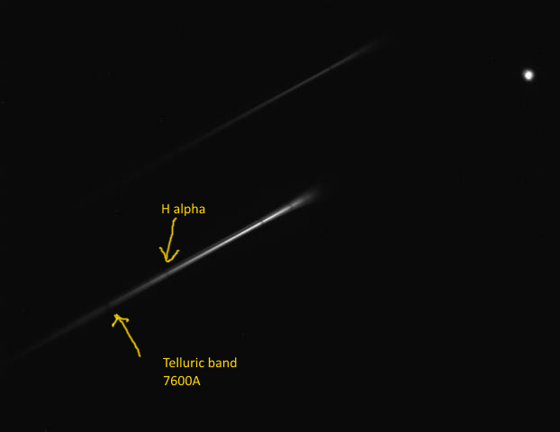
I have marked the O2 Telluric band at 7620A on your image. There is nothing useful beyond that as it overlaps with the 2nd order spectrum. You can fit the spectrum including this line and the zero order horizontally across the image at your current spacing.
Cheers
Robin
 27 March 2018 at 10:38 am #579262
 Peter TaylorParticipant
Thanks for all the info Robin, that has sorted it all out.
peter
-
AuthorPosts
- You must be logged in to reply to this topic.
