› Forums › Spectroscopy › More Lhires III mods
- This topic has 49 replies, 5 voices, and was last updated 7 years, 8 months ago by
 Robin Leadbeater.
-
AuthorPosts
-
27 March 2018 at 2:07 pm #579263
 Alun HalseyParticipant
Jack
I had to adjust the white screws on the collimator body until the belt stopped slipping. In fact I took one of them out completely leaving just the one to add tension to the body. Other than that,and the velcro added to the motor shaft nothing has been stuck to the collimator body. One other point now that you have removed the cover/door I would be more inclined to block off the gaps that have now been introduced around the lens body so as to stop dust getting to the grating itself. Got the idea from Paul Lukas (second photo down)..
http://jazzistentialism.com/blog/?page_id=1397
Regards
Alun
28 March 2018 at 10:33 am #579264 Mr Jack MartinParticipant
Alun,
Thanks for the link, some good modifications.
I can put one cover back on once I have got the belt gripping properly, will try putting o rings over the lens thread.
The Lhires is contained in a film changing bag which should keep dust and light out.
A question, as I do not operate the spectrograph remotely is there any point in motorising the micrometer arm ?
Regards,
Jack
Essex UK
28 March 2018 at 10:35 am #579265 Mr Jack MartinParticipant
Alun,
Which side did you remove the screw from the collimator body ?
Regards,
Jack
Essex UK
28 March 2018 at 2:36 pm #579267 Alun HalseyParticipant
Jack
Had a play with my setup last night and found that there was a slight play between the collimator body and its supporting frame so have now replaced the screw (was the one on the motor side) but have it screwed in just touching the collimator body to prevent unwanted tilt but at the same time not adding any force to tighten the turning of the body. All adjustment for tension on the collimator body is carried out by the screw on the opposite side.
I motorized the micrometer shaft so that I didn’t have to touch any of the kit during a session and I also run remotely so comes in handy. But the downside is the speed of the focus motor makes moving the grating from the Hb region to the Ha region painstakingly slow 🙁
Regards
Alun
28 March 2018 at 10:28 pm #579268 Robin LeadbeaterParticipant
Hi Alun,
Unwanted movement of components is a significant issue in spectrographs and the the tolerances are very small. (1/5 pixel (~1um) shifts are easily detectable.) The LHIRES design is particularly prone to these problems. Have you checked by aiming the spectrograph in different directions (NSEW,Zenith) and watching the position of the lamp lines that your mod is not introducing any additional unwanted instability ?
Cheers
Robin
29 March 2018 at 9:49 am #579269 Alun HalseyParticipant
Hi Robin,
Yes I have checked in all directions and found no shift at all in the lines. There is a slight shift when using the motor to focus (much the same as if I were manually focusing) but this can be reduced as I stated earlier by adjusting the tension of the screw on the collimator body support opposite to the motor,once the unit is focused everything is stable.
Regards
Alun
29 March 2018 at 3:39 pm #579271 Robin LeadbeaterParticipant
That’s good news. I see measurable flexure with my LHIRES even with everything done up tight. It was one of the early kit ones so perhaps I should take it all apart and rebuild it !
29 March 2018 at 8:05 pm #579275 Mr Jack MartinParticipant
Alun and Robin,
Thanks for your advices.
I will take measurements as suggested.
A tear down sounds like a good idea which should sort any instability problems.
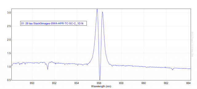
1. There is a problem with wavelength shift any idea what’s causing this see attached.
2. The calibration lines are in focus at start and can go out of focus at the end of the session.
Both problems occur on and off, before motorising the collimator lens adjustment, I don’t expect that to make any difference.
Has anyone else had these problems ? if so how did you overcome them ?
Regards,
Jack
Essex UK
 30 March 2018 at 2:04 pm #579281
 Alun HalseyParticipant
Jack
Not had any problem in that respect regarding shifting/loosing focus of the neon lines but have read about the possibility of the collimating lens having a loose fit within its cell.
Regards
Alun
30 March 2018 at 3:39 pm #579282 Andy WilsonKeymaster
Hi Jack,
I’ve seen both of what you describe.
I found that depending of the angle of the spectrograph due to gravity, then there can be small wavelength shifts. Nothing to cause a serious problem during normal observing, though on a run lasting over an hour might then the overall resolution could be slightly reduced. The tests I did were about 3 years ago and I’m not sure I’ve still got a copy. With the spectrograph off the telescope I took neon calibration images with the spectrograph on each side and vertical, to observe the most extreme effects. I then made careful measurements of the centres of the neon lines at the same position on each image.
It might be worth making sure all the screws in the body of the LHIRES III are tight, but I think small shifts are to be expected. There is more than one moving part and heavy cameras attached. Only a minute flexure will cause a small shift in wavelength. That is one reason why fibre fed spectrographs can be more stable, though using optical fibres introduces a different set of problems.
I also see shifts in focus with temperature. So on a cold night if I start with the neon lines in perfect focus then often they won’t be in perfect focus at the end of the run. This is again something I live with. The flat fields will be slightly compromised, but if I refocus then that would also compromise the flat fields. Of course as long as you retake the flats after each refocus then that is not a problem. This is the same behaviour as needing to refocus a telescope due to thermal contraction from falling temperatures.
Best wishes,
Andy
30 March 2018 at 5:52 pm #579283 Robin LeadbeaterParticipant
Another area to look at is the grating holder. I noticed one of mine was much worse than the other. One of the holes in the metal plate that the brass rod ran though was slightly oval and the springs on both of them were rather weak and were probably not taking up all the play in some orientations. I put an extra turn on both of them which improved things. If you have the removable grating type holder, check there is no slack causing the grating to move. (It needs to be just tight enough to clamp the grating but not too tight otherwise you risk distorting the grating which shows up as astigmatism)
I have also heard tell of one case where the mirror came lose (It was stuck with double sided tape in the original kit, not sure if this applies to the factory built versions) Also check that the screws hold the mirror mounting (both the adjusting screw and the pivot) are done up tight too.
Also the position of the neon relative to the slit affects the position of the calibration lines so check it is centred over the slit and comes to the same place each time.
If your calibration lines move back and forth as you rotate the doublet check that the lens is seated correctly in its holder. (The original kit had two fibre washers, one either side of the lens. I removed one so the lens seats directly against the metal holder on one side, Similarly I removed the plastic foot from the micrometer so there is direct metal contact which stopped some cyclic movement in the lines as the micrometer was adjusted.
All this relates to the early kit though and may have been improved in later versions.
Robin
2 April 2018 at 6:01 pm #579291 Mr Jack MartinParticipant
Thank you all for your input, lots to consider here.
Almost finished motorising the collimating lens, I wrapped a 3 mm wide strip of Velcro round the edge of the lens which grips the belt and works best at fastest rotation speed setting on the handset.
I will test the system and make any changes as necessary as per your suggestions.
Once complete, this should be a more user friendly set up and relatively cheap to convert.
Regards,
Jack
Essex UK
2 April 2018 at 6:08 pm #579292 Mr Jack MartinParticipant
Alun,
The collimating lens worked loose in my Lhires but is easy to fix.
I advise Lhires users to check just in case.
Regards,
Jack,
Essex UK
11 April 2018 at 5:28 pm #579323 Alun HalseyParticipant
Received the JMI motor focuser from Rother Valley Optics this morning so got to work attaching it to the Lhires in place of the Skywatcher motor. Just a case of removing a cog and the attachment that goes on a focuser knob and adding a small cog wheel (donated once again from the printer I broke up) to the motor shaft, also had to make up a smaller diameter belt,luckily had just enough printer belt left to do this. Works a treat,not as bulky as the Skywatcher motor and is lighter,just need to add small cover over the cog so as to seal from light and stop dust getting in slot.
Regards
Alun

 27 April 2018 at 6:36 pm #579382
 Mr Jack MartinParticipant
Alun,
That’s a neat mod with the smaller motor.
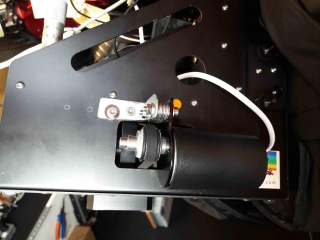
Attached is a pic of my finished mod with the Skywatcher motor.
I tried it out on Sunday night and got double calibration lines l l (don’t have a pic) when I took the drive belt off and focused manually it settled down to give single calibration lines l .
What’s causing this to happen ?
Regards,
Jack
Essex UK
 28 April 2018 at 1:04 am #579386
 Alun HalseyParticipant
Jack
Not had this happen with either motor (Skywatcher or JMI) so not sure what has gone wrong to cause the double lines. Clutching a few straws here, seems there could be the possibility that distortion is somehow introduced between the collimator body and its support. How tight have you got the tension on the belt? Only need a small amount,just enough to allow belt to grip the collimator body and turn it but feels slack if you pinch belt either side of the cog. Have you used the white screws in the support to alleviate any possible side to side movement, lastly did you have to join the belt, if so have you watched the lines as the belt turns and noted where the join is (being as the belt will be slightly thicker in the region of the joint tension on collimator body will increase slightly).
Hope you get it sorted!
Regards
Alun
4 May 2018 at 7:53 pm #579431 Mr Jack MartinParticipant
Alun,
The belt is fairly taught to turn the collimator with a Velcro layer wrap around for grip.
The white screws are slackened off 1/2 turn or so from tight to prevent side movement.
The belt is not joined.
I have adjusted both again and will see how it works tonight, and will report back.
Regards,
Jack
Essex UK
5 May 2018 at 9:48 am #579435 Alun HalseyParticipant
Jack,
I cannot see your attachment,but still baffled as to what could be causing the doubling of the line. I have not seen the effect in my setup at all. The only thing I can think of once again is that the belt is too tight and placing the lens slightly out of line,maybe my using a much thinner belt places less pressure on the setup. Have you tried using a replacing the belt with a rubber band? Maybe the velcro round the collimator body is the problem (I have just placed belt round the body and have no slippage).
Regards
Alun
9 May 2018 at 6:40 pm #579434 Mr Jack MartinParticipant
Alun,
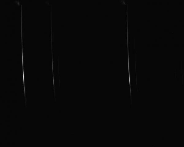
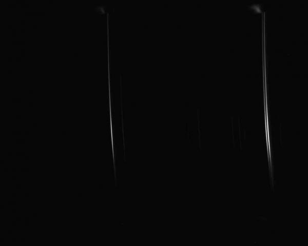
Attached last nights calibration frames taken around H alpha line.
Far right double line with belt on, collimator screws loose to allow belt to rotate lens, same far right single line with belt off, collimator screws tightened and focused.
Any thoughts as to why only 1 calibration line is double and what’s causing this ?
Regards,
Jack
Essex UK

 9 May 2018 at 6:41 pm #579452
 Mr Jack MartinParticipant
Alun,
I have uploaded the pics again.
Regards,
Jack
Essex UK
-
AuthorPosts
- You must be logged in to reply to this topic.
