Forum Replies Created
-
AuthorPosts
-
 Robin LeadbeaterParticipant
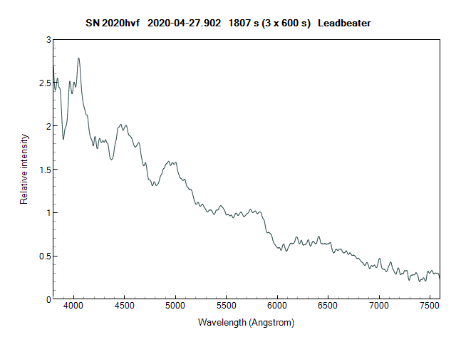
This is an interesting one. It was discovered very early back on 21st April and is just hitting maximum light now. I took a spectrum on 27th April but could not then get a good match using the SNID classification software I usually use, possibly because it does not have many early spectra to compare with. Current spectra give a good match to type Ia now though and the brightness is bang on where it should be for a type Ia. Here is my spectrum (also in the BAA database as usual) and there is a more current spectrum here on the ARAS forum
http://www.spectro-aras.com/forum/viewtopic.php?f=38&t=2519
Cheers
Robin
 Robin LeadbeaterParticipant
How about a proper PCI board parallel port if you can fit one? They seem to still be available for 64 bit and up to win 10 eg
https://www.startech.com/uk/Cards-Adapters/Parallel/1-Port-EPP-ECP-PCI-Express-Parallel-Card-~PEX1P
Robin
 Robin LeadbeaterParticipant
That is my simple small dish setup using currently used sat TV frequencies. I think the big ones used lower frequencies (C band ?) and I believe are good for making Hydrogen line receivers if you can find one (more popular in the US I think)
 Robin LeadbeaterParticipant
Hi Kate,
Spectral classification is a rather inexact science as many stars show anomalies which don’t fit neatly into the simple MK classification system. As a result you get different opinions for the classification even for non variable stars (Variable stars can change their classification with time for example due to temperature changes caused by pulsations)
A good source for spectral classifications is Brian Skiff’s huge catalogue which has all the published classifications with the references for currently approaching a million stars
http://vizier.u-strasbg.fr/viz-bin/VizieR?-source=B/mk
Here we see for sigma Boo a range of classifications dating from 1897 to 2001
F4V kF2 mF1 is the latest one and comes from a paper by Richard Gray who is famous in stellar classification circles and for example co-authored the current “bible” on the subject “Stellar Spectral Classification” by Gray and Corbally
The paper referenced is here
http://simbad.u-strasbg.fr/simbad/sim-ref?bibcode=2001AJ….121.2148G
There he notes that sigma Boo is metal weak and looking in the footnotes to table I (page 2155) he explains the multiple classification nomenclature he has used. So for sigma Boo we have a metal weak star with the traditional classification F4V, presumably based on the Balmer lines but based on the strength of the Ca II K lines it looks like an F2 and based on the metal line spectrum it looks like an F1
Robin
 Robin LeadbeaterParticipant
Unless otherwise explicitly stated I always assume events organised by humans are in the organiser’s local time. It has not let me down yet 😉
In this case however the browser is changing the time shown on the website to the readers local time which in my view cannot be a good idea.
 Robin LeadbeaterParticipant
A big welcome to all Reality Titbit readers from all at the British Astronomical Association 🙂
13 April 2020 at 6:55 pm in reply to: Forum “Last Post” button and new posts getting lost up the thread #582279 Robin LeadbeaterParticipant
Hugh Allen posted yesterday showing its continuing spectroscopic evolution on the way back to “normal” in reply to an earlier post of mine
13 April 2020 at 4:28 pm in reply to: Forum “Last Post” button and new posts getting lost up the thread #582276 Robin LeadbeaterParticipant
Also if a new reply is added up the thread, the numbering of all posts in the thread below it are all incremented even though they were posted earlier so you cannot reference a post by its number
 Robin LeadbeaterParticipant
Hi Hugh,
Nice series !
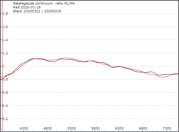
I tried to merge your spectra with mine as they appeared to show the same trend but ran into difficulties intially. I then compared our spectra on similar dates and saw some differences in the continuum shape (Perhaps due to different technique. To beat down the scintillation I summed multiple short exposures rather than defocus and I used a different reference star HD36777). No matter though as the ratio is consistent so it should be possible to reconcile our two series of spectra and combine them to give full coverage from before minimum
 Robin LeadbeaterParticipant
OK so having examined the spectrum images it appears that the uptick in the spectra at the red edge is due to an additional component superimposed over the correct spectrum. This is seen as faint region at the top of the spectrum seen as a lump in the cross sections to the right of the unchanged main cross section profile. See also the attached image.
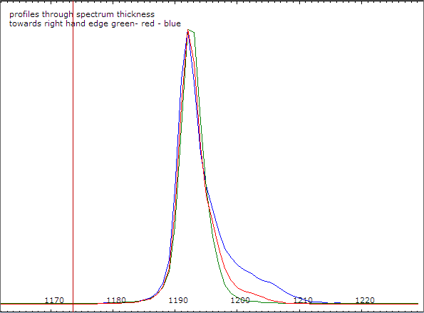
The origin is unknown. (suggestions welcome) but a working hypothesis (to be tested) is a second order overlap but that is surprising to me at least at this wavelength
Robin
 Robin LeadbeaterParticipant
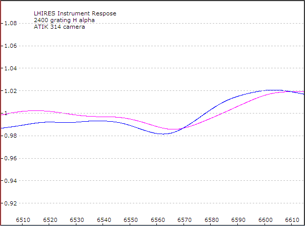
Here are a couple of typical responses for my setup (they differ by less than +-1% and are flat within +-2% . I suspect the dip in the middle is due to slight inaccuracies in the removal of the reference star H alpha profile rather than a real effect. (The graph is 1360 wide compared with the camera 1391 so just 31 pixels trimmed off somewhere)
Cheers
Robin
 Robin LeadbeaterParticipant
“I would have thought that, as long as it’s clear what you do (I uncheck the IR box on the dbase entry, and insert appropriate comments in the header) its OK to use an uncorrected spectrum?”
I think we first need to find out why your instrument response is not consistent and independent of the reference star, which it should be if nothing is changing. Otherwise you could be seeing similar variations in your target spectra.
Once that is sorted you can chose not to make an instrument response correction but in my view the spectrum should then be rectified and the flag set in the header rather than post a non calibrated spectrum, otherwise you leave the lamp spectrum imprinted on the continuum
Cheers
Robin
 Robin LeadbeaterParticipant
My LHIRES H alpha spectra are not normally cropped (well perhaps a few Angstroms at the very edge) but my camera might be narrower than yours (an ATIK 314) so perhaps yours is wider and you have some vignetting after the grating, though the flat should still take care of that
Robin
 Robin LeadbeaterParticipant
Hi Kevin,
changes in atmospheric dispersion chromatic aberrations are unlikely to be the cause over such a narrow range in the red. I have certainly never seen any effects as great as this with my LHIRES. Provided you are doing a flat correction, moving the mirror should just move the spectrum up and down, and perhaps alter its brightness due to vignetting but not alter its shape. The instrument response should essentially just be the flat lamp spectrum ie for a halogen lamp in this part of the spectrum a very gentle smooth slope. (Even placing the star at a different position along the slit should not be a problem provided a flat correction is done, although it is good practise to place the star in the same position)
Is there anywhere you can upload your raw image set to (eg dropbox etc) and I could take a look ?
Cheers
Robin
 Robin LeadbeaterParticipant
Cloudy here but I grabbed a frame off an all sky camera (University of Hertfordshire http://observatory.herts.ac.uk/allsky/ ) and compared it with the same date and time a year ago. See attached. A crude comparison but the relative brightness of Megrez looks roughly the same to the camera at least
Cheers
Robin
 Robin LeadbeaterParticipant
 Robin LeadbeaterParticipant
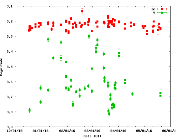
B,V Ic correspond to the band in which the brightness was measured. (The survey instrument uses a CCD camera and wide field lens). V corresponds roughly to what the eye sees Ic is the near infrared. There are small long term average trends from season to season but the variation from day to day/week to week of up to 0.5 magnitudes seen in the V data would be obvious by eye if real. The very tight error bars on the points would suggest they are real but I am somewhat sceptical.
 Robin LeadbeaterParticipant
Is the short term variation in KWS V mag real ? eg
 Robin LeadbeaterParticipant
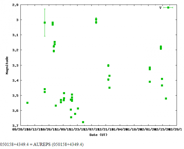
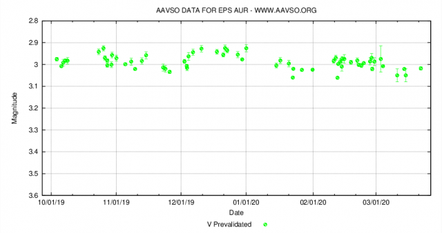
Interesting that the variability in I is much less than in V. Reminiscent of the recent Betelgeuse fading
 Robin LeadbeaterParticipant
I was taking spectra last night and the signal from the target suddenly disappeared. I went outside to check and as far as I could tell the sky was completely clear. I went back inside and watched as the signal came back up. Half an hour later the same thing happened but this time I looked outside to find it was foggy, putting an end to observations
-
AuthorPosts

