Forum Replies Created
-
AuthorPosts
-
 Robin LeadbeaterParticipant
– Calibration – still having problems in getting Demetra to ‘automatically’ recognize the calibration image and to properly assign the right spectral line. When I use ‘automatic’ I cannot get better than 2.4 RMS, where if I go in an manually set the lines to the image (5852, 6562, 6965, 7067, 7383) my calibration gets a very good .2-.8 RMS.
Yes these automatic systems tend to either work or fail catastrophically. (I often tell the tale from my other life in paper technology where we had developed a sensor which used a neural network to measure a property using the NIR spectrum. It was trained on a range of products and worked flawlessly….. until one day it started producing compete nonsense. It turned out the manufacturer of one of the materials used in the paper had made a subtle change in the formulation which he had not told us about !)
I can’t help with Demetra, though at Francois Cochard’s zoom workshop meeting on calibration, I did promise to try it!
https://www.youtube.com/watch?v=vijEMrow0hQ
(ISIS has an automatic function which works flawlessly for me with my ALPY and LHIRES, though unlke Demetra it does need some manual input to tune it initially and you need to point it to the approximate position of one line, then it can find them all)
Cheers
Robin
 Robin LeadbeaterParticipant
Well the sensor would not have much sensitivity that far into the IR but the star in question is the bright (V mag 6.6) star V419 Cep / HD203380. It is spectral class M2i which will be about 3x brighter at 1000nm compared with in the visual so pretty bright where the filter is transparent.
Robin
 Robin LeadbeaterParticipant
As here for example
http://www.astrosurf.com/buil/filters/curves.htm#Astronomik%20Visual%20OIII
OK for visual use but most of these would need an IR block with a CCD camera
Robin
 Robin LeadbeaterParticipant
Hi David,
That was my first thought but this is reported to be a narrow band image in [OIII]. Though perhaps it is possible that the filter leaks in the IR?
Cheers
Robin
 Robin LeadbeaterParticipant
Hi Keith,
David mentioned MILES stars. I find a good way of checking the quality of ones observations is to measure a few of these stars and compare the results directly with the spectra as measured professionally. Any differences can then be investigated and once they are close to the professional version one can confidently submit spectra of other targets to the BAA database for example. You can see an example of this sort of test here using the ALPY 600.
https://britastro.org/node/8153
and there are more examples and further information here on my website
http://www.threehillsobservatory.co.uk/astro/spectroscopy_21.htm
Cheers
Robin
 Robin LeadbeaterParticipant
Hi Hugh,
Time to place our bets on which way it will go next season !
A comment from Paul Roche in January:-
“It’s not obvious what’s going on here, as the declining EWs for H alpha and HeI suggest a diminishing disc, but the AAVSO photometry seems to suggest the opposite. We’ll have to keep an eye on things for the rest of the “X Per season” and see if it makes sense when we have a bit more data. It will be interesting to see how the (B-V) and (V-R) colour of the system is behaving, that might reveal a little more about the state of the disc”
There is very little data in other bands in the AAVSO photometry data. Does your continuum data show any colour trends ?
Cheers
Robin
 Robin LeadbeaterParticipant
There are now over 230 spectra in the BAA spectroscopic database. Thanks to all contributors ! Continuing monitoring on a nominal 2 week basis during the next season is requested. The following is a quick analysis of a selection of the available spectra.
The fall in EW of both the H alpha and He 6680 lines plateaued during January 2020 and remained constant up to the last recorded spectra on 2020-04-06 so there was no complete loss of the disc, though the He line in particular became very weak at just -0.4A EW
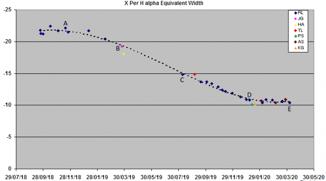
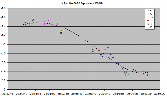
A snapshot of 5 heliocentric corrected line profiles during the monitoring period (marked A-E on the EW plots) shows the complex evolution of the lines and although the EW was approximately constant from Jan to April 2020, the line shape continued to evolve.
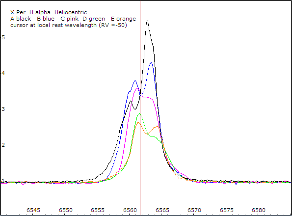
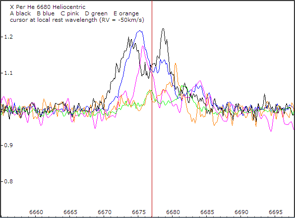
Although noisy due to the weakness of the line, there are significant differences in the He 6680 line profile compared with the H alpha line with higher radial velocity features particularly on the red edge.
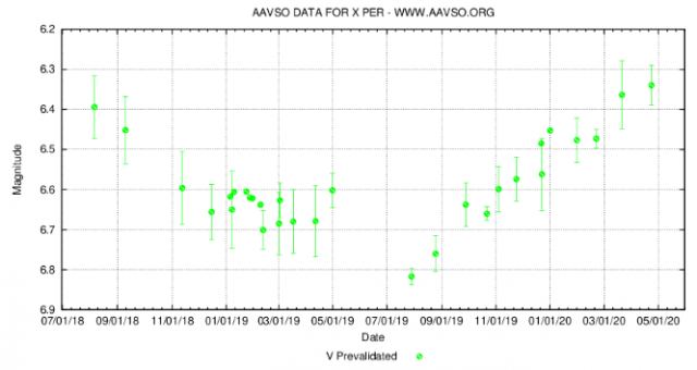
Here is the AAVSO V mag light curve for the same period. There is no obvious correlation
Cheers
Robin
 Robin LeadbeaterParticipant
The same would apply if using the G channel from a DSLR to estimate the V mag of the nova as the G channel response at H alpha is different again eg
http://www.astrosurf.com/buil/50d/test.htm
Robin
 Robin LeadbeaterParticipant
I remember Gordon Myers talking about transformations (and extinction) at the 2018 BAA/AAVSO joint meeting.
https://britastro.org/video/13862/14771
He put some numbers to the size of the effect for different systems he tested (6:39)
At the end of the day though these are still approximations dependent on the actual spectrum and can be way out in some circumstances. As an extreme (though real) example, a Nova spectrum dominated by H alpha. eg
https://britastro.org/specdb/data_graph.php?obs_id=650
A significant fraction of the H alpha flux would appear in the standard Johnson-Cousins V passband but would be completely missed by the Chroma version. Spectroscopy is much more straightforward 😉
Robin
 Robin LeadbeaterParticipant
Hi Andrew,
I thought Bessell was pretty much the same as Johnson-Cousins eg here half way down the page
http://spiff.rit.edu/classes/phys440/lectures/filters/filters.html
Of course the elephant in the room is the response of the sensor which is very different today compared with detectors of previous eras
Robin
 Robin LeadbeaterParticipant
The response curve of those Chroma filters
https://www.chroma.com/products/sets/27103-bessell-ubvri
looks very different from the Baader (and other) versions I’ve seen
http://astrograph.net/Baader-Planetarium-Johnson-/-Bessel-V-Filter-125-and-50mm-x-50mm
Robin
 Robin LeadbeaterParticipant
Christian Buil has an interesting CCD/CMOS comparison. Though specifically concentrating on spectroscopy,he covers camera noise, amp glow and linearity
http://www.astrosurf.com/buil/CMOSvsCCD/index.html
With high resolution spectroscopy of faint objects at the limit of detectability the sky signal is insignificant so camera noise becomes the most significant source of noise. To minimise read noise contribution, exposure lengths used with CCD are typically >1200sec and it takes many hours to get a sufficiently noise free stack of darks, though cloudy nights can be used of course!
Although low, the read noise in CMOS is not insignificant and once the typical slit width relative to pixel size is considered, is not that different from that of good CCD because of the ability to bin pixels with CCD so there is not much latitude for combining shorter exposures with CMOS (though an spectrograph optimised specifically for the small pixels found in common CMOS sensors could perhaps avoid this). The thermal noise is also typically higher for CMOS cameras which need much lower temperatures to match that of a CCD so although the performance gap is not large these days, CCD still appears to have the edge in performance (Though not in cost per area) when used with currently available commercial spectrographs.
Cheers
Robin
 Robin LeadbeaterParticipant
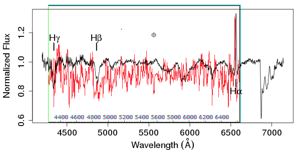
With the help of Thomas Bayes perhaps I can now claim to have previously detected both the Balmer H beta absorption with emission core and H alpha emission 😉
My rectified spectrum from 2020-05-30 (red) overlaid on the spectrum published in the Atel
(I also see the problem of not being able to insert images. I had to press “preview” before I got the “insert” option)
Robin
 Robin LeadbeaterParticipant
OK here are the spectra for 2020-05-29 and 30.
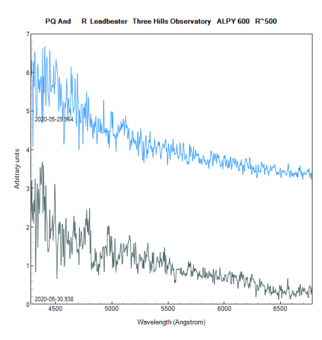
Apart from the hot continuum there is nothing common between them so unfortunately the details are probably just noise. They were taken at 5 deg altitude (air mass 10) in a bright sky though so to be honest it was a surprise to get anything
 Robin LeadbeaterParticipant
Hi Jeremy
Should supernova spectroscopic observations be reported independent of their inclusion in the database? (SN 2020ue mentioned has 22 spectra and SN 2020hvf has 5 in the database currently and there are recent spectra of 4 other supernovae)
Cheers
Robin
 Robin LeadbeaterParticipant
And the spectrum against the bright sunlight, strong telluric lines and auroral and atmospheric sodium emission lines.

Note how the spectrum curves down towards the blue end due to the strong atmospheric refraction. Not sure if I can extract much of use from it but it was fun trying !
 Robin LeadbeaterParticipant
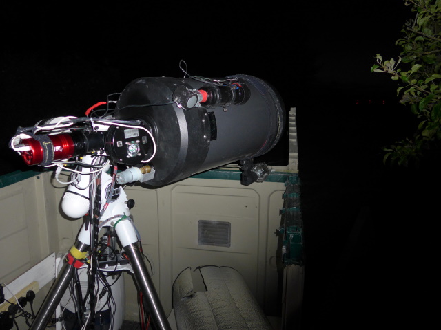
Here it is in the spectrograph guider a few minutes ago (at 5 deg altitude !)
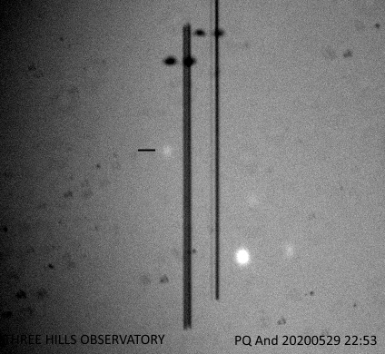
 Robin LeadbeaterParticipant
A tough one. I’ve put out an alert on the main spectroscopy forums. It is (just) circumpolar for me and I although I do have a decent (though currently bright) horizon directly north, I lose it behind a tree as it climbs in the dawn sky
 Robin LeadbeaterParticipant
Hi Graeme,
You definitely need to set up an annulus of some width to measure and subtract the background. If not, as Andy says you include light from the galaxy (and light pollution etc) with the supernova in the brightness measurement. Too narrow though and the background level measurement becomes noisy. To wide (or too far out) and it becomes unrepresentative of the background where the target is. Perhaps you could try annuluses (annuli?) of different non zero widths and see how much the result varies ?
 Robin LeadbeaterParticipant
Yes the sky background has to be subtracted somehow. The same problem crops up in spectroscopy of supernovae and some programs have various ways of fitting a model to the sky background in the surrounding region. In my limited experience of photometry I think programs which model the star point spread function against the background work better in this situation, though there could still be a bright/or dark patch directly under the target of course. The transient survey instruments get round this problem by subtracting an image taken when the transient was not there.
Robin
-
AuthorPosts
