Forum Replies Created
-
AuthorPosts
-
 Derek RobsonParticipant
Yes, I’ll draw a diagram and post it. Just bear with me.
 Derek RobsonParticipant
I slept on that one and awoke with an optics headache, hmmmm. “why) the distance along the laser beam changes the measured dispersion”. I’m not sure now. I was thinking about what is it that we are seeing when looking at a LASER beam. I have a vague memory that you can’t or shouldnt be able to see them, except if the beam is blocked by something. I think that the visible beams are due to reflections from illuminated particles in the air. Am I right in assuming that the first order “beams” that we see, are not really there in the air (unlike the pointer beam)? That is, the first order beams are constructed from an infinitesimal number of diffractions from the same number of sources of illumination along the primary beam going outwards to the chimney pot? And the light is diffracted after the grating, so doesn’t happen in the air outside, but rather, in the camera? On the parallelism, I started to think what the LASER beam would look like in the following two situations a) the beam is normal to and horizontal to the grating and sensor. I’d expect to see a dot on left and on right side, with dispersion distance “A”. But if we tilt the LASER to say 45 degrees upward (pointing to a roof top), how would the diffracted dots appear in the spectrum? (the LASER would be hitting the grating at 45 degrees tilt. Would the dots be dispersed by a distance B which was smaller or larger than A? or should A = B always (whatever the distance; but might differ with tilt)? Is that what you meant? It has me baffled. Could geometry solve it?
 Derek RobsonParticipant
The beams look like they are not parallel between zero and 1st order. But I thought that’s the way the physics worked – the light is diffracted through an angle relative to the incident light. I’ve done a series of repeatability tests by firing LASERs at roof tops and aerials (in the dead of night) and will be looking at the spread of the distances from the zero order. But this is on dots, not the beams. I’m looking at the target as the source of the LASER light coming back to the sensor. Some images on the wide angle lens show the beams at angles. But we know even parallel roads will join together in the distance (perspective). I’m measuring the position of the diffracted dot relative to the zero order dot. That should show if there is any non linearity in the wavelength range I guess. Another problem is, the diffraction gratings are plastic, so they are not rigid, and can bend, causing curved spectra (curvature along the wavelength axis). But despite that variation, I hope that will be insignificant and not interfere significantly, or at all, with identifying elements.
 Derek RobsonParticipant
I haven’t processed the images in BASS, ISIS or RSpec yet (I don’t have RSpec but maybe get it). Just by eye, looking at the green, red and blue LASERs, the first order diffraction falls into that colour along a spectrum of Vega or Sirius. I read recently of one of the astro spectroscopists who did the opposite of what I did. He measured the wavelength of a green laser with a spectrophotometer using a calibration lamp. For a green laser he used, he was spot on to within 0.1 nm of the stated wavelength, and that result was probably well within the experimental error of the determination. I don’t know how much they vary in quality between products. I’ve read that many are reliable in wavelength and bandwidth. Isn’t the process required to stimulate the radiation the same i.e. it is a specific atomic de-excitation that causes the light, and it’s energy (frequency or wavelength) is well-defined by chemistry and physics of the energy levels of the elements used in the LASER. Green and blue tend to be of one wavelength, whereas red ones fall into more than one category of wavelength, depending on which one it is. That was a problem I encountered with my red LASER, I didn’t know which it was, but it was a standard collimation LASER. For the purposes of identifying elements in meteor spectra, I think they are still likely to do the job because some element lines can be identified relative to each other, even if the calibration is out a bit or a lot.
 Derek RobsonParticipant
I will add cobalt, nickel, and titanium and vanadium to the list – that is, if I can get the thing to work and add a camera, so a long term project which can be dipped into. The data will build up. I’ll have to check that I have some vanadium and titanium, but if not, I may have a steel with some in. But obviously better to have the pure stuff so I know all the lines come from one element. The amounts in steel are often such that the spectrum will be dominated by iron, and some lines will be difficult to see if they are not as intense. Anyone got any pure vanadium and titanium? I’ll gratefully accept a small chunk, plate. Just has to be a surface area of at least 2 inches.
 Derek RobsonParticipant
It’s a beautiful spectrum. It reminds me to use the arc spectrometer I mentioned, obtain some pure iron (or as close as one could get in the iron grades) then obtain a spectrum. It’s an old spectrometer which I need to work out how to fix a camera to record the spectrum over the full wavelength range. I have somewhere, a spectrum of iron and all the major lines already printed in a fold out booklet of several A4 pages long (there are a lot of lines with relative intensities). I will get that copied. It would be nice to discover some exotic elements. But because of the binding energies of the atoms, there is a minimum which occurs around the atomic weight of iron, which I think? means iron is expected to be predominant in abundance (in the nuclear fusion processes of stars), next to cobalt and nickel in the periodic table. I will run cobalt and nickel. Might take me some time because I need a suitable connection to the spectrometer – if it still works?
 Derek RobsonParticipant
 Derek RobsonParticipant
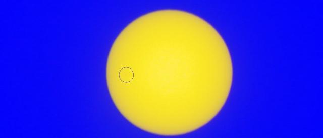
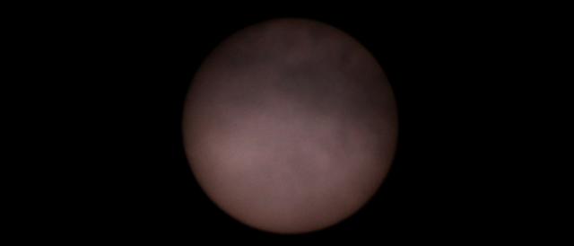
 I decided to try for it.
Taken with a DSLR 70-300 mm lens set at 300 mm f5.6, with an aluminised Mylar filter I’d made for the total solar eclipse in 1999. Taken through a double glazed window, with a towel over my head to see the live screen.
1 November 2019 at 3:23 am in reply to: Videos of the Spectroscopy Software Training Workshop #581547 Derek RobsonParticipant
These are great to be able to go through and replay at my leisure and pace. Thanks for putting them up, a great complement to the Workshop itself.
 Derek RobsonParticipant
I wondered what you do with the slides, negatives once scanned? Do you keep them? I’m aware of silver halide photos have been used as an archiving method (lasts 100 years or more). I assume?? the slide/negative plastic might last longer than a digitised copy file on computer storage media (and media that can be read – e.g. because of the way computers change, the files would have to be transferred to newer and newer storage media, to keep a usable copy). The original slides could be scanned again and again (unless they become so brittle, that they fall apart). I don’t think I could throw out my slides and negatives (IF they were scanned), though probably wouldn’t ever use them again. Hard to let go but it would create a bit more space.
 Derek RobsonParticipant
Hi Robin.
Thanks for all that, some more readings and videos.
“These different types of event have characteristic spectral features and are very different from what the spectrum would have been before the explosion.”
It would be someone’s lucky day had they just recently randomly acquired data on a random star before and then heard of an event, then went to analyse it again on the same kit. But then, there would probably be no reason to have targeted though, unless there had been suggestions of activity.
Derek
 Derek RobsonParticipant
Excellent capture. Digitised spectrum looks really good.
 Derek RobsonParticipant
Supernovae can be seen visually. So what extra does spectroscopy do? Is it that spectra of supernovae can be used to classify them, in a similar way that spectra of stars can classify the stars into certain spectral types?
When a stars goes supernovae, is there a change in spectra (composition wise) before and after?
 Derek RobsonParticipant
Hi Bill
It is good to see someone willing to extract spectra from this old film negative. To have captured that spectrum on film 22 years ago was an excellent achievement. I too was surprised at a response of unmeasurable. It looks like a spectrum that can be digitised. I wasn’t aware there could be non linearities but surely that could be compensated for with calibration checks, or, could relative ratios of certain wavelength pairs along the spectrum, be checked to help confirm linearity or not? [of course, one needs to identify the peaks though].
I recall reading an article which included a picture of a spectrum of a meteor imaged by Harold Ridley which said it was believed to be the first in the UK. I can’t remember if the article was in the BAA journal, or the smaller sized booklet that they used to publish and provide as an insert to the journal. I know I have that in my collection of magazines.
You’ve done an excellent job at extracting the spectra. Some differences in composition? I look forward to the findings.
 Derek RobsonParticipant
Tony. I may get to the stage of getting a second Watec video camera, this time, for meteor spectroscopy. I would need a grating and fittings to place in front of the lens. I’m sure my astro colleagues can help on the fitting aspect, but if you have the items I’d need for that type of work, I would be interested.
-
AuthorPosts
