Forum Replies Created
-
AuthorPosts
-
 Robin LeadbeaterParticipant
It could also be worth exploring pixels sizes more widely either side. With my setup (an ATK428, smaller but with same size pixels) I get a good lock and calibration (RMS 0.13A) for 2x binned pixel sizes between 8.90 and 9.06 for a nominal 4.54×2 = 9.08. Using the 3123/(difference in pixels between H alpha and H beta) formula, I get 9.02 which is towards the top end of the lock range
(I was going to attach an example lamp image for comparison but max allowed size is 2Mb and zipped files are not allowed. Can you send me your image via email to robin_astro (at) hotmail.com please)
Robin
 Robin LeadbeaterParticipant
Hi John
Yes that is the right reference line. ISIS should definitely work with the camera you have and the method I suggested, I use it all the time. (The high errors means ISIS is failing to find and lock onto the correct lines)
Can you check that the smile correction has worked correctly please. Run the calibration on the lamp spectrum itself instead of the target star, ticking sky background not removed. (you will need to put a 1 on the end of the file name so ISIS sees it as the first of a series) If you then examine the image (“display image”) in the page you get after pressing go, the lines should be vertical and straight.
Can you also post the original image as a zip file please and I will see if I can get it to work this end.
Cheers
Robin
 Robin LeadbeaterParticipant
Hi John,
Does it work ok with just the calibration lamp? ie without the wizard,ticking “predefined mode” “ALPY (calibration module)” in “general” and entering the position of the 5852 line in “calibration”
Robin
 Robin LeadbeaterParticipant
Yes, that’s great.
Thanks !
 Robin LeadbeaterParticipant
Hi David,
Yes I saw your image. These are really useful as it helps with finding the target and spotting useful nearby guide stars. It is annoying I could not pin down exactly what type it is. I have had some feedback from a professional using a different fitting program on my spectrum and he favours it being a type 1c. This would makes sense as a 1a-91T-like should be significantly brighter at this distance, though that could be down to extinction.. Hopefully I will get another go before it fades too much and perhaps it will have evolved enough to pin it down.
Cheers
Robin
 Robin LeadbeaterParticipant
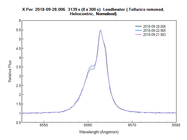
Changes in H alpha over past 6 days
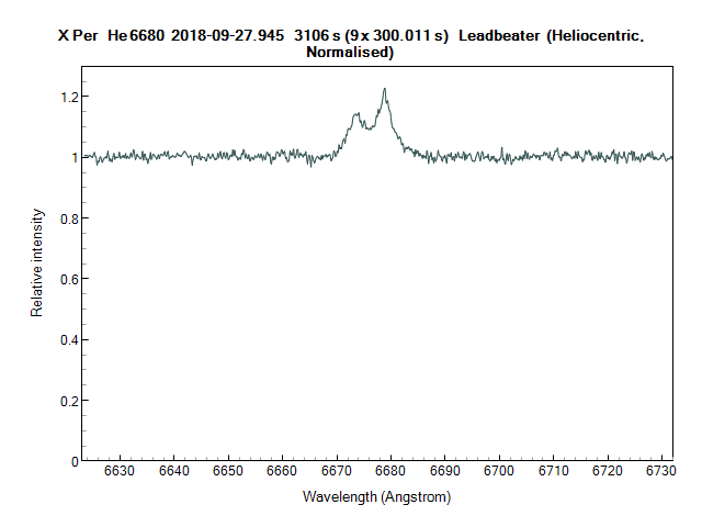
The He I 6680 line (approximately 15x weaker than H alpha)
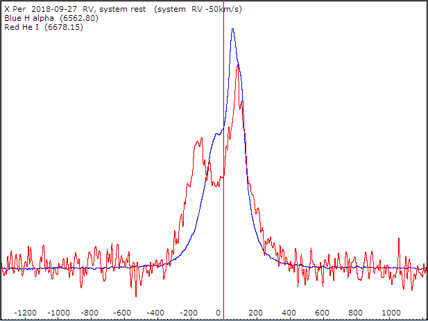
Radial Velocity of both lines (km/s, plotted in system rest frame)
Cheers
Robin
 Robin LeadbeaterParticipant
Meteor spectroscopy is possible with the Star Analyser and a wide field camera
http://www.threehillsobservatory.co.uk/astro/spectra_20.htm
but a grating with higher dispersion would be better eg 300 or even 600 l/mm depending on the lens focal length and sensor size. Bill Ward would be able to advise on the optimum setup
https://britastro.org/user/213
Cheers
Robin
 Robin LeadbeaterParticipant
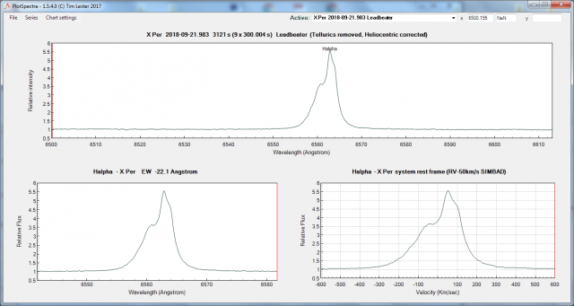
Here is how the H alpha line looks currently. (LHIRES 2400 grating, R~15000). Also uploaded to the BAA spectroscopic database
Robin
 Robin LeadbeaterParticipant
Hi Paul,
I think he sort of did 😉 You could PM for details
19 September 2018 at 6:57 pm in reply to: New RCB star in Cam – call for photometry/spectroscopy #580016 Robin LeadbeaterParticipant
Latest feedback from Gabriel Murawski based on the spectrum is that this may in fact be a YSO. It is currently being looked at by experts in this area.
Robin
 Robin LeadbeaterParticipant
I have posted some information specifically about spectroscopy in the spectroscopy section
https://britastro.org/node/15540
Robin
 Robin LeadbeaterParticipant
Hi Tony,
the ARAS forum has a new for sale section now, “Petites Annonces” though there are not really many constructors there.
The astronomical_spectroscopy yahoo group probably has more self builders and I see there was a recent ad there for an L200 for example, you could check with Ken who owns the group if it would be acceptable
Also Stargazers Lounge perhaps where there is some interest in spectroscopy ?
Robin
 Robin LeadbeaterParticipant
According to BeSS, it is not catalogued as a Be star unfortunately otherwise there would undoubtedly have been a good history of H alpha spectra of this bright object. Does anyone know why it is not in the Be Star catalogue ?
Robin
 Robin LeadbeaterParticipant
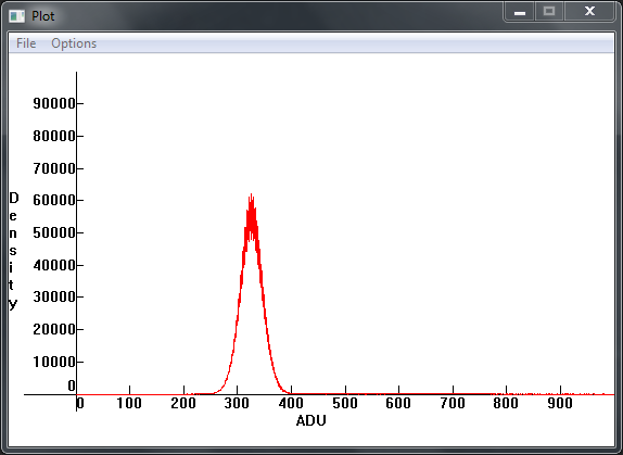
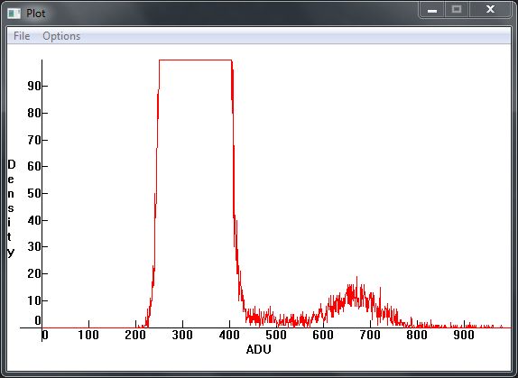
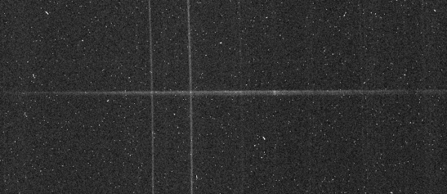
Looking in detail at the distribution of these warm pixels in my camera it seems most of them fall between 500-800 ADU, causing the “knee” in the cumulative distribution described in the ARAS thread. They are in fixed positions and only represent ~1 in every 2000 pixels though and are low enough to be corrected by a dark provided they are otherwise well behaved.
Robin
 Robin LeadbeaterParticipant
Hi John,
Here is a link to a dark taken under the same conditions as yours using my ATIK 428. This camera is identical except for using a smaller version of the same CCD so should be a direct comparison.
https://drive.google.com/file/d/1QkocrvkQRBCOlTK9NbxOhSVxWMwM7COg/view?usp=sharing
If you have ISIS, it includes a nice feature which you can use to calculate the gain, and noise figures described here
http://www.astrosurf.com/buil/isis/noise/result.htm
These warm pixels are not specifically measured using this technique though. To get the dark current figures quoted by ATIK and measured by Christian Buil, you have to chose a measured area free of warm pixels.
Robin
 Robin LeadbeaterParticipant
Hi John,
I remember there was some discussion on the ARAS forum about the long tail of warm pixels seen in cameras with Sony CCD which seems to have got progressively worse with each generation.
http://www.spectro-aras.com/forum/viewtopic.php?f=8&t=1919&p=9871
I recently saw an article somewhere which suggested this was a characteristic of CCD with anti-blooming, a connection had not been aware of before.
Discounting these, the noise figure of these CCD is very good though and they seem to respond well to dark subtraction.
Running at a lower temperature might help. I run my similar ATK428 at -10C all the year round.
Robin
 Robin LeadbeaterParticipant
A potential target for a spectrum. mag 15 is just about bright enough for a standard ALPY 600 and a modest (say> 10 inch) aperture.
Robin
 Robin LeadbeaterParticipant
Hi Woody,
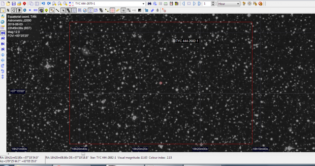
I have it on my list but have not had a chance to look at it yet. It looks a very crowded field. I make it this one in centre of the DSS image. Is that correct ? From VSX J2000 18 20 12.99 +07 15 52.1
Cheers
Robin
 7 September 2018 at 4:02 pm in reply to: New RCB star in Cam – call for photometry/spectroscopy #579972
 Robin LeadbeaterParticipant
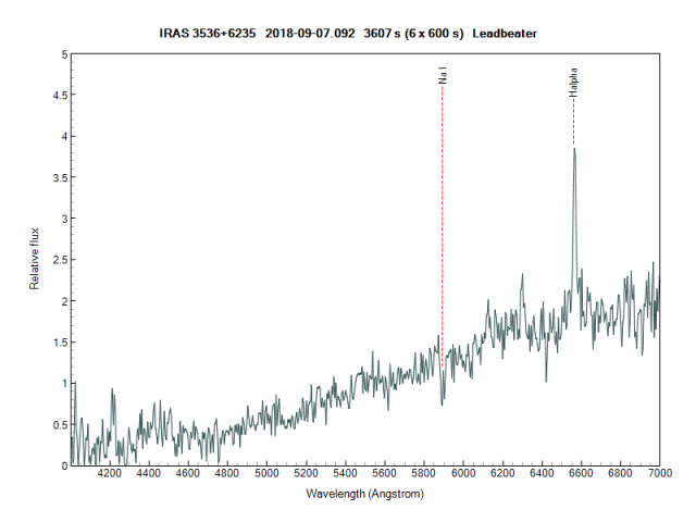
Here is the reduced spectrum. Very noisy but the H alpha emission is clear. The continuum is very red but there is high extinction in this direction. Total galactic E(B-V) is ~1.0 according to IRSA. The Na D line is clear but again that could be Interstellar.
Robin
 7 September 2018 at 3:58 am in reply to: New RCB star in Cam – call for photometry/spectroscopy #579969
 Robin LeadbeaterParticipant
On it now with the ALPY600. It is very weak but there is clear H alpha in emission. Raw spectrum image (30min) attached
Robin
-
AuthorPosts
