Forum Replies Created
-
AuthorPosts
-
 Robin LeadbeaterParticipant
One other thing that could be worth checking is that the servo controlled reflector is set so the calibration lamp is shining directly down on the slit. If the slit is illuminated at a significant angle, it can cause small shifts relative to the star spectrum. (I’ve not heard of this with the ALPY but I suspected this problem with the original manual LHIRES system)
Cheers
Robin
Robin LeadbeaterParticipantOK, I think the constant shift with just the lamp confirms that there was some shift in the spectrograph (It is very small. I think 3A equates to about 5um or about a pixel). The changing temperature might have been a factor. With the ALPY I usually take a lamp spectrum each time I change target during an observing run even though I normally dont see any shift during the night. (With the LHIRES I see a lot of movement so I take a lamp spectrum at start and end on every target and every half hour or so during long exposures but it is much less stable thermally and mechanically than the ALPY)
Cheers
Robin
Robin LeadbeaterParticipantOK John,
ISIS seems to have found the lines ok and the fit looks good. I am wondering if there has been some sort of shift between the lamp spectrum and the star spectrum. With the mixed Balmer and lamp line calibration you are using, the lines used for calibration up to 4861 (H Beta) are the Balmer lines in the star and the lines higher than that are from the calibration lamp. Normally the ALPY is very stable but if everything is not quite tightened up, there could have been a shift between the star and lamp exposures. Did you take the lamp spectrum under the same conditions as the star ?
Can you also run the calibration using just the lamp lines ? If there was a shift, we should then see all the Balmer lines shifted, not just H alpha
Cheers
Robin
Robin LeadbeaterParticipantOK I have checked the MILES zet Dra spectrum and the Balmer lines do appear to be at the expected wavelengths ( eg 4861, 6563A) There will be small adjustments to make for the radial velocity and heliocentric correction but these will not add up to as much as 3A so there looks to be something going on here. Can you post a copy of what ISIS reports in the “Go” window please?
Thanks
Robin
Robin LeadbeaterParticipantHi John,
I am not sure the wavelength calibration of the MILES stars is all that accurate. I remember seeing some apparent discrepancies when I was trying to do some radial velocity work. Do your individual errors for the lamp lines look good particularly those bracketing the H alpha line? (from the report that ISIS generates in the “Go” window. )
I would not worry about adjusting the Grism further if ISIS is finding the lines to do the wavelength calibration OK (The RMS error should be low, <0.5A and there should be no obvious larger errors in any individual line as reported by ISIS)
The kink in the instrument response of the ALPY around 4000A is real and often seen, though the cause is not clear. See my recent post here for example.
https://britastro.org/comment/5542#comment-5542
Cheers
Robin
Robin LeadbeaterParticipantIn this case though what we need is the geometric median which minimises the distance travelled. My first student vacation job was with the GPO, writing a computer program to decide where the international exchange should be sited to minimise cabling costs (distance from exchanges, weighted by the traffic). I think it came out near Reading (This was in the 60’s and the computer CPU time was charged by the second)
Robin LeadbeaterParticipantKevin does have a valid claim to the centre of population though.
Robin LeadbeaterParticipantI filter the spectra to match the resolution and shift them slightly if needed to line them up before division. With MILES spectra the match is generally very good then and little editing is needed (I edit out any artifacts rather than choosing points on the curve as that way I can smooth less and include more subtle effects in the instrument response. eg as here)
https://britastro.org/comment/5542#comment-5542
Cheers
Robin
Robin LeadbeaterParticipantDefinitely the normal (ie the original) spectrum from MILES for response correction. You want the original spectrum as it was measured, not what it would look like without interstellar exinction. (When you see MILES referenced in literature it is usually the dereddened spectra as it is normally used for modelling of stellar populations in galaxies but fortunately for us the raw uncorrected spectra were also made available)
Cheers
Robin
Robin LeadbeaterParticipantHi David,
This is a good technique I sometimes also use if I suspect there has been a shift in focus during a long run. My setup suffers from chromatic aberration which can affect the response depending on focus due to selective sampling of different wavelengths by the slit as here for example.
https://britastro.org/comment/5542#comment-5542
Robin
Robin LeadbeaterParticipantHi John,
The error in calibration for a given altitude difference depends on altitude. The best match would be to the mid point altitude but in practise except at low altitudes the error is small for 5-10 deg difference in altitude. For more details see my recent post here
https://britastro.org/comment/5536#comment-5536
The ARAS forum link there gives links to Francois Teyssier’s spreadsheet for choosing reference stars which includes MILES and other potential stars and takes the error into account. There is also a chart linked from the ARAS post showing error relative to altitude.
Cheers
Robin
Robin LeadbeaterParticipantFrom Francois Teyssier’s “Low Resolution Spectroscopy Observers Guide” list of principal lines in symbiotics p 41
http://www.astronomie-amateur.fr/Documents%20Spectro/SpectroscopieBasseResolution_En.pdf
Cheers
Robin
Robin LeadbeaterParticipantHi Tony
Can you track the rogue pixels down in the raw images? If it is in every image then it should have been in the master dark and corrected but you could add it to the cosmetic file and zap it that way.
I dont know about BASS but the ISIS cosmics removal tool works on the individual sub exposures where a rogue pixel stands out more clearly than in the combined spectrum image. It compares each pixel with its neighbours, looking at the differential between each pixel and the surrounding ones. You can set the threshold so if a pixel is poking its head above its neighbours, ISIS will zap it. (If you set it too low though, particularly if the spectrum is close to undersampled, it can zap a whole row or spectrum line so you have to use it with caution)
Robin
Robin LeadbeaterParticipantHi Hugh,
Yes the acid test is to rerun the reference star using the calculated instrument response
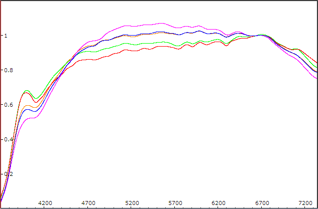
If the flat has done its job well the instrument response should be nice and smooth (just the flat lamp spectrum and atmospheric extinction plus any wavelength selective sampling at the slit due to chromatism) I am not sure if BASS does this but ISIS even assumes a black body curve for the flat lamp so in theory with ISIS ideally all you should be left with is the atmospheric extinction. With my LHIRES at H alpha high resolution this results in a dead flat instrument response within a couple of percent every time so it is hardly worthwhile doing an instrument response correction. In practise with my ALPY there are some small ripples at a couple of percent from the sensor response which the flat has not quite dealt with and a rather nasty kink to deal with around 4000A. I am not sure where it comes from but others have also reported it. Perhaps the reflectivity of the paint used on the reflector used in the ALPY calibration module ? Note the variation in shape in this collection of my IR curves. A lot of this I believe is due to chromatic aberration in my focal reducer coupled with slight differences in focus.
 Robin LeadbeaterParticipant
Hi Nick,
Are you saying that ISIS is not finding the dark and flat files you entered in the general page when you run the data reduction?
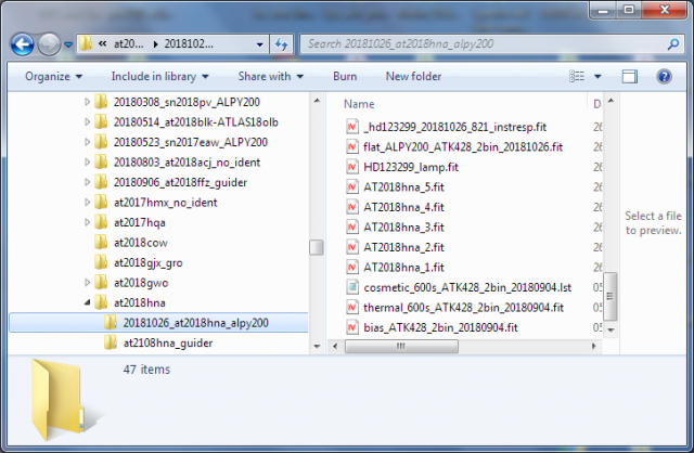
I have developed my way of working with ISIS over several years so I probably don’t do things the standard way. I collect all the files ISIS needs to do a data reduction in one folder titled with the target name and date, copying the masters, instrument response and wavelength calibration files etc in from other folders if necessary, rather than have ISIS search for them in different folders. (See attached example from a run last night) That way, although there is some duplication of files, I can archive the folder and always rerun the reduction again using the same set of files in the future. When I run the reduction I point ISIS to that folder in the settings page and point to the individual files in that folder the general page.
Robin
 Robin LeadbeaterParticipant
Hi Nick,
Are you looking for A or B stars in general or specifically ones suitable for use as reference stars?
If the latter, then for low resolution spectra the MILES stars (included in the ISIS database) have actual spectra associated with them or alternatively Francois Teyssier has generated a list of hot main sequence stars with low interstellar extinction which can be used (with caution) with generic spectra from the Pickles library. You can find his spreadsheet which also includes the MILES stars and has tools to help with selecting stars close to the target here
http://www.astronomie-amateur.fr/Documents%20Spectro/ReferenceStarFinder.xlsm
with more information in this post on the ARAS forum
http://www.spectro-aras.com/forum/viewtopic.php?f=6&t=821&p=3697#p3697
Cheers
Robin
Robin LeadbeaterParticipantA reminder that spectra to BeSS standard normally do not have telluric lines removed or heliocentric corrections applied so it is important to make these corrections before comparing them. (I remember seeing a poster by a professional which claimed to show features moving in a line profile which were in fact due to telluric lines in heliocentric corrected spectra !)
Robin
Robin LeadbeaterParticipantSimilar variability is also seen in the He 6680A line.
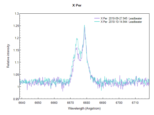
Although the line is much weaker, the variability is actually greater as a percentage compared with at H alpha
Robin
Robin LeadbeaterParticipantHi Kevin,
You could well be right. I was looking at the variability the other day, using some from the BAA database and some I had been sent direct.
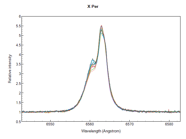
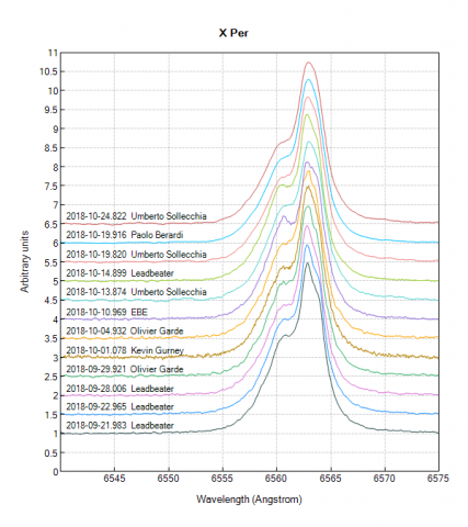
The spectra are good quality and there is good coverage so it might be possible to characterise the variability. There is some sign of rapid variations, even from day to day though so any period might be rather short. It might be worthwhile doing a run over a full night and looking at the short term variability.
Robin
25 October 2018 at 12:34 pm in reply to: A confirming spectrum for Nova in M31, TCP J00420310+4102331 #580086Robin LeadbeaterParticipantThanks Andrew,Andy,
I am starting to wonder if this might be an amateur first. Does anyone know of any other amateur extragalactic nova spectra ?
Robin
-
AuthorPosts