Forum Replies Created
-
AuthorPosts
-
 Robin LeadbeaterParticipant
Jack said
“I am awaiting Robins response on this one.”
Hi Jack,
Not sure what this relates to. What do you want to know ?
 Robin LeadbeaterParticipant
Hi Jack,
It is a fits spectrum profile to BeSS standard as used in the BAA database for example (Are you trying to open it as an image?) It will open in VSpec, ISIS, BASS etc. (change the extension from .fits back to .fit if you are having difficulties)
Cheers
Robin
 Robin LeadbeaterParticipant
Hi Jack,
Spectrum profiles (in fits or dat format) are also small enough to be uploaded as attachments here if you need advice and are not ready to submit them to the database. For example here is my latest for VVCep at the blue end. It is a work in progress as I am not 100% happy yet with the instrument response/atmospheric extinction correction so I have not yet committed it to the database. (Note I had to change the extension from .fit to .fits as the forum does not accept .fit )
Robin
 Robin LeadbeaterParticipant
Hi Andrew,
I see your name correctly in the forum and on your members page or am I not looking in the right place?
Robin


 Robin LeadbeaterParticipant
Hi Jack
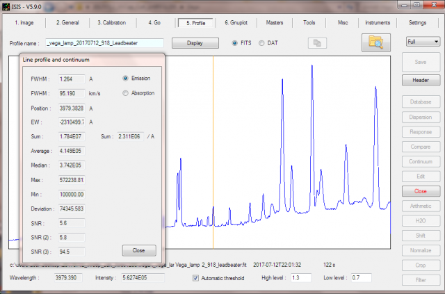
ISIS automatically estimates the resolving power from lamp line widths for you and adds it to the fits header (SPE-RPOW) or if you want to manually measure it (for example on different lines across the field) you can produce a spectrum profile using the lamp image and measure them directly using the FWHM function.

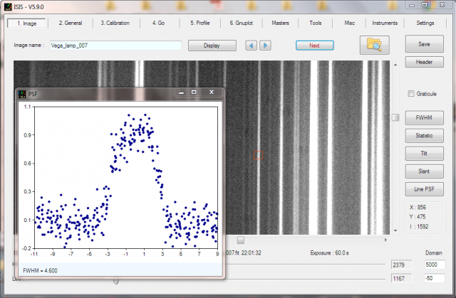
In ISIS you can even measure the width of the lines (in pixels) directly off the image using the PSF function – useful for checking if you have best focus.

Cheers
Robin
30 July 2017 at 11:44 pm in reply to: Keeler’s seminal paper on the spectroscopic observation of nebulae #578410 Robin LeadbeaterParticipant
Fascinating. The description of the slanted lines in Jupiter’s spectrum due to rotation is familiar. It was one of the first things I looked at when I built my LHIRES III !
Ken Harrison recently pointed me to an on line version of another interesting historic document
“An Atlas of Representative Stellar Spectra 4870 to 3300” William Huggins published 1899
http://www.e-rara.ch/zut/content/titleinfo/15851436
An interesting parallel to Richard Walkers publication
Cheers
Robin
 Robin LeadbeaterParticipant
It is interesting to estimate the net difference in flux between Marc’s and Jack’s setup. (A C11 with a 35um slit compared with a C14 with a 23um slit.) at 3 arcsec the slit throughput is 70% and 40% respectively but because of the higher collecting area of the C14 the difference in flux is reduced. The net effect is the total flux after the slit should be quite similar (Jack’s is ~5 % lower) Jack’s resolution will be ~50% higher though because of the narrower slit.
A good estimate of the actual resolution can be made from the FWHM of the internal calibration lamp lines.
Robin
 Robin LeadbeaterParticipant
Hi Marc,
I am not sure where the throughput being proportional to the square of the slit width comes from. There are trade offs between slit width, SNR and resolution but the change in throughput with slit width depends on various factors. Ignoring diffraction effects, for an extended source the increase would be proportional to the slit width but with a stellar source it depends on the FWHM of the star image relative to the slit width. A good guide is to aim for a slit width equal to the star image FWHM. With a slit wider than that you are gaining little in throughput but losing resolution. If the slit is set narrower you will increasingly lose more throughput but you may prefer to take the resulting increase in resolution if you still have enough signal to still give the required SNR.
Regardless of the camera or gain, shorter exposures means fewer photons and thus higher shot noise (which dominates at high SNR). There is no free lunch here
Robin
 Robin LeadbeaterParticipant
There is a nice calculator for this on the CAOS website
https://spectroscopy.wordpress.com/2009/05/22/slitpinhole-flux-calculator/#more-525
which I believe is incorporated in to Ken Harrison’s modified version of Christian Buil’s simspec, the spectrograph design spreadsheet. Plugging in the values for my setup (C11 at f10 and 3 arcsec seeing) it calculates 50% throughput at 23um, 70% throughput at 35um and 85% throughput at 50um slit width. I normally run a 35um slit.
Note that other variables such as guiding accuracy and position of the star on the slit can be as, if not more important though. The definitive test as to how much light you are using is to measure the flux of the spectrum of a star with and without the slit. (or in the narrow and wide parts of a photometric slit of you have one)
Cheers
Robin
27 July 2017 at 3:53 pm in reply to: Measuring radial velocity of planetary nebulae with Alpy? #578384 Robin LeadbeaterParticipant
Impressive RV precision ! There are various interesting physical properties that can be measured from spectra like this. Francois Teyssier has a worked example on his website
http://www.astronomie-amateur.fr/feuilles/Spectroscopie/NGC2392.html
Robin
26 July 2017 at 2:16 pm in reply to: Measuring radial velocity of planetary nebulae with Alpy? #578376 Robin LeadbeaterParticipant
Hi Paul,
There are some examples of its use with ALPY here which might be useful
http://www.astrosurf.com/buil/redshift/demo.htm
EDIT:
Also described in the ISIS change log under v5.1.0
http://www.astrosurf.com/buil/isis/new/release.html
Cheers
Robin
26 July 2017 at 12:15 pm in reply to: Measuring radial velocity of planetary nebulae with Alpy? #578374 Robin LeadbeaterParticipant
I think my limited work with the ALPY suggested a few tens of km precision but high RV precision using low resolution instruments is certainly possible though for example as David demonstrated at a BAA workshop using a LISA a couple of years back with if I remember, an impressive 5km/s 1 sigma ?
Robin
26 July 2017 at 11:58 am in reply to: Measuring radial velocity of planetary nebulae with Alpy? #578372 Robin LeadbeaterParticipant
Hi Paul,
a 200km/s error with the ALPY does seem unexpectedly large (roughly a pixel or so). Like you I find the ALPY very stable and I would expect to be able to measure the position of a strong narrow line in an extended object like a PN to better than say 1/5 pixel. In stellar RV work one source of significant error is the position of the target on the slit. (if the star is too small it “rattles” in the slit and even if overspilling the slit, slight offsets in guide position alter the shape of the line profile and move the centroid.) I would not expect these issues with PN though as they are effectively extended objects. Since the error is variable we can also rule out an offset in the calibration lamp spectrum. PN are expanding so show different RV depending on the area examined but I understand these are only a few tens of km/s at most.
I dont know the quality of the wavelength measurement on Plotspectra. Have you tried measuring the lines in ISIS? Also since the ALPY calibration is so stable and you are comparing the PN using lines at the same wavelength, you could try just overlaying the raw uncalibrated profiles of the two PN and look for any shift directly to eliminate any potential errors in wavelength calibration.
Cheers
Robin
 Robin LeadbeaterParticipant
Hi Paul,
It is a bit tricky to tell as the final version is a combination of the two on line documents. “Analysis and interpretation of Astronomical spectra” and “Practical Aspects of Astronomical Spectroscopy” Also the on line copies I have are probably not the last versions that Richard published (mine are v8.6 and v2.0 respectively). Perhaps Marc has a better idea of what has been added/changed significantly. Alternatively a comparison of the list of contents might show up any obvious differences.
Cheers
Robin
 Robin LeadbeaterParticipant
Just as clarification, CUP gave me complementary copies of these two books in return for my views on the market for amateur astronomy books in general and on spectroscopy in particular which they asked me about this some time ago.
I have long been a fan of Richard Walker’s Atlas in its free on line format for many years and I was pleased to find that CUP did a good job transferring it to print.
I do have some reservations about the accompanying “Spectroscopy for Amateur Astronomers” though which is based on two other on line documents previously published by Richard. It is a useful reference book with a good list of references for further reading but the practical parts are somewhat limited to what Richard has worked on in preparation of his atlas and may have benefited from wider input from other experienced amateurs . For example the use of flats and difficulties of flux calibration he mentions are areas which, while tricky subjects, have largely been successfully tackled by other amateurs. I would have preferred these areas and other areas to have been addressed head on in more detail rather than just put in the “too difficult for amateurs” category.This is my personal view of course which I did convey to CUP when they originally asked for my comments on an early draft.
Robin
 Robin LeadbeaterParticipant
No C2 bands or emission lines then ?
Robin
 Robin LeadbeaterParticipant
A small correction:- Umberto used an ALPY 600 but Paolo used a LHIRES with 150l/mm grating giving a similar resolution.
Robin
 Robin LeadbeaterParticipant
Hi Marc,
It is indeed possible to perform absolute flux calibration of spectra using photometric magnitude measurements as a reference (as opposed to just calibrating the spectra relative to the continuum). It is a technique frequently used by amateurs these days to calibrate broad band (typically low resolution) spectra where an absolute flux calibration is required. The details of the method were developed on the ARAS forum. Tools were built into ISIS software and the procedure was formalised by BAA member here, David Boyd.
http://www.spectro-aras.com/forum/viewtopic.php?f=8&t=897
and has been used in several of his (peer reviewed) papers in the BAA Journal.
It is not strictly valid to use the technique in the way Ernst has done here however as the spectral range covered is not the same as that of the V filter passband The implicit assumption here is that the flux in the V band and in the continuum at H alpha are linearly correlated. This is not always the case and would need to be established, for example by performing simultaneous photometry in V and R bands.
Alternatively more conventional techniques for absolute flux calibration of spectra are also used by amateurs by recording spectra of spectrophotometric standard stars, aided for example by the use of dual width “spectrophotometric” slits available for the Shelyak spectrographs which allow the total flux to be collected. This does need stable atmospheric conditions however during the observation. (analagous to all sky photometry). Again ISIS software has the tools to enable this.
http://www.spectro-aras.com/forum/viewtopic.php?f=8&t=695
Cheers
Robin
 Robin LeadbeaterParticipant
Hi Matt,
Magnitude is a log scale so v(target)- v(comparison) is actually the ratio of the intensities of the two stars, which is independent of the actual count/intensity scaling in the image.
the magnitude of the comparsion star is itself a ratio (To a standard star with vmag =0 eg Vega)
Cheers
Robin
 Robin LeadbeaterParticipant
Hi Marc,
I assume BASS estimates the resolution in a similar way to ISIS by estimating the FWHM of the neon calibration lines, in which case it may not give a good estimate of the resolution on undersampled spectra like this. (Not enough points in the line profile)
There is still something odd about the dispersion value. The native dispersion of the LHIRES 2400 at H alpha is ~12.8A/mm so for example giving 0.083A/pixel with my ATIK314 (6.45um pixels) Your native dispersion should be around 0.06A/pixel so it looks like there is a further 3x binning going on somewhere. In any case I suspect you are losing some resolution compared with other LHIRES III 2400 spectra of the same object. Compare for example the cleanly resolved metal/telluric lines in similar spectra on the ARAS forum as here for example.
http://www.spectro-aras.com/forum/viewtopic.php?f=19&t=362
It seems that H alpha is likely to be well covered so I might take a look in the UV. With the potential for variation in size of both the H alpha disc and the M star. It could be important to establish the extent of the M star independent of the disc. It is a more difficult area to work in but I had some success in this area with the similar but much fainter eclipse of AZ Cas
http://www.threehillsobservatory.co.uk/astro/spectra_43.htm
There is a discussion involving Phil Bennett about this area here
http://www.spectro-aras.com/forum/viewtopic.php?f=19&t=1233
Cheers
Robin
-
AuthorPosts
